laboratorioFW
This library provides the mapping between the Franzininho WiFi board pinout and the activation pin codes of the Embedded Systems and IoT Laboratory board, along with examples for using the peripherals available on the board.
Click here to access the library repository on GitHub.
How to Install the Library
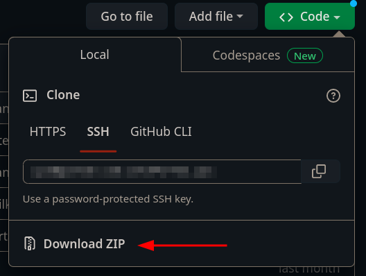
- Download the library in zip format by clicking Code and then Download ZIP
- Open the Arduino IDE
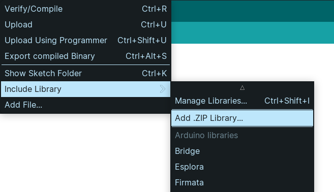
- Go to Sketch > Include Library > Add .ZIP Library
- Select the downloaded zip file and click OK
- Optional: Look for library examples in File > Examples
How to Use the Library
To use the library, simply include it in your code file with the line #include<laboratorioFW.h>. After that, you can use the board's activation pin codes in your code.
Important: The digits in the activation pin code are separated by an _ character — i.e., activation pin C0 can be accessed in the code through the code C_0, and so on.
Usage Example:
#include <laborarotioFW.h>

#define led A_1

void setup(){
    pinMode(led, OUTPUT);
}

void loop(){
    digitalWrite(led, HIGH);
    delay(1000);
    digitalWrite(led, LOW);
    delay(1000);
}
Implemented Examples:
testes_completos.ino
This example contains all the code needed to test all the peripherals available on the board. This code is for board validation and is not meant for everyday use.
adivinhe_a_senha.ino
In this example we implement a password verification system using the matrix keypad and the Keypad library to map the keyboard. The user must enter a five-character password using the board's matrix keypad. When the user indicates they have finished entering the password by pressing the button corresponding to * or #, the sequence is compared to a password predefined in the code. An LED turns on to indicate whether the password is correct, and a message with this information is printed to the serial monitor.
ativar_led_RGB_com_potenciometro_e_botoes.ino
In this example the goal is to control the brightness of the RGB LED using a potentiometer and three buttons. The three buttons are used to select which color of the RGB LED will be controlled (red, green, and blue) and the analog reading of the potentiometer is used to adjust the intensity of the selected color.
ativar_servo_motor_com_botoes.ino
In this example, we use two buttons to control the position of a servo motor. The buttons are associated in the code with left and right directions and change the servo angle, making it possible to move it in both directions. The ESP32_S2_ISR_Servo library was used.
contagem_display_7seg.ino
In this example, we use the seven-segment display to show a count from 0 to 9 seconds.
controle_led_com_ldr.ino
In this example, we read the LDR sensor and map the reading to a value used to turn on an LED. The example also has a button that controls an internal program state and selects whether the reading will be printed as read or with complementary logic.
do_re_mi_fa.ino
In this example a song is played by the buzzer together with the activation of the addressable RGB LED. The program uses the Adafruit_NeoPixel library to control the LED.
genio.ino
In this example, we implement the Simon game (also known as Genius). In this game, four LEDs are activated in a randomly generated sequence and this sequence is presented to the player, who must repeat the sequence in the correct order by pressing the corresponding buttons. When the LEDs light up, a corresponding sound is played by the buzzer.
leitura_do_teclado.ino
In this example we read a key pressed on the matrix keypad and print it to the serial monitor. The Keypad library is used to map the keyboard.
leitura_sensores_externos.ino
In this example we read the external sensors connected to the external connector sockets on the board and print the read values to the serial monitor.
leitura_sensores_grove.ino
In this example we read the external sensors connected to the Grove connectors on the board and print the read values to the serial monitor.
leitura_umidade_temperatura_oled.ino
In this example we read the temperature and humidity sensor and write the data to the OLED display. The DTH and SSD1306Wire libraries are used.
movimentar_elemento_oled_joystick.ino
In this example we use the OLED display to show an asterisk that can be controlled by the joystick module, moving it around the display. The SSD1306Wire library was used.
This project was developed as part of the Final Graduation Project of Letícia Pegoraro Garcez.