Pin Identification in the Arduino Environment
In ST's documentation, STM32 microcontroller pins are identified by names such as PA1, PA2, and PB6 (as can be seen in the Franzininho C0 schematic). Here we describe the identifications used in the Arduino Environment.
This information refers to the "Generic STM32C0" board option in the STM32duino package. In the future we hope to have a board-specific option for the Franzininho C0, using more appropriate default options for the pins.
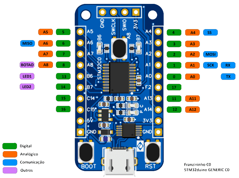
The figure below summarizes the identifications:
The STM32duino package accepts identifications of the type PA1 as pin "names", but this is not the usual identification in the Arduino environment.
Digital Input and Output
For digital input and output, the Arduino environment uses numbers to identify the pins. The figure at the top of the page shows the numbers corresponding to the Franzininho pins.
Digital functions also accept the names used for analog input (see the next item).
Analog Input (ADC)
For analog input, the Arduino environment uses names of the type An. The figure at the top of the page shows the names corresponding to the Franzininho pins.
Asynchronous Serial Interface (UART)
The microcontroller in the Franzininho C0 has two asynchronous serial interfaces (uart1 and uart2). It has some flexibility in connecting these interfaces to the pins.
In the Arduino environment, asynchronous serial interfaces are accessed through objects with names such as Serial, Serial1, and Serial2.
In the Franzininho C0, pins PA9 and PA10 are connected to the CH340 USB-to-serial converter to provide serial communication with a computer through a USB cable.
The "Generic STM32C0" option defines a Serial object associated with the uart1 interface, using pins PA0 and PA1 (as shown in the figure at the top of the page). To use the Serial object to communicate via USB, you need to reconfigure the pins through the setRx and setTx methods before calling the begin method (see also the "Hello World" example):
  Serial.setRx(PA_10_R);
  Serial.setTx(PA_9_R);
  Serial.begin(115200);
Note: The special names for pins PA9 and PA10 are due to the fact that these pins share the same physical pins as PA11 and PA12.
To use uart2, you need to declare a Serial2 object and specify the pins to be used:
HardwareSerial Serial2(uart2);

  Serial2.setRx(PA3);
  Serial2.setTx(PA2);
  Serial2.begin(115200);
SPI
The figure at the top of the page indicates the pins used by default for the SPI interface, accessed through the SPI object that is part of the standard SPI library.
See details in the SPI example.
I^2^C
In the Arduino environment, the I^2^C interface is accessed through the Wire object, which is part of the standard Wire library.
The "Generic STM32C0" option uses pins PA9 and PA10 as defaults for the I2C interface. Since these pins are connected in the Franzininho C0 to the USB serial converter, you need to reconfigure the pins through the setSCL and setSDA methods before calling the begin method (see the "I2C" example).
Valid Options for Pins
UART1
| Signal | Options |
|---|---|
| TX | PA0, PA9, PB6, PC14 |
| RX | PA1, PA8, PA10, PB7 |
UART2
| Signal | Options |
|---|---|
| TX | PA2, PA4, PA8, PA14 |
| RX | PA3, PA5, PA13, PA14 |
SPI
| Signal | Options |
|---|---|
| MISO | PA6, PA1, PB6 |
| MOSI | PA2, PA7, PA12, PB6 |
| SCK | PA1, PA5, PB6 |
| SS | PA4, PA8, PA14 |
I2C
| Signal | Options |
|---|---|
| SCL | PA9, PB6, PB7 |
| SDA | PC14, PA10, PB7 |
| Author | Daniel Quadros |
|---|---|
| Date: | 19/10/2023 |