How to Simulate the Franzininho DIY on Wokwi
Wokwi is an online simulator for Arduino and Electronics. It was built for makers, by makers.
You can use Wokwi to learn to program the Franzininho DIY, prototype your ideas, and share your projects with other makers.
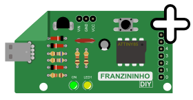
Use the Franzininho DIY Template by clicking the image above to start a new project on Wokwi.
Getting Started
Let's start our program by turning on the LED1 of the Franzininho DIY in the simulator. Copy or type the code below into the Wokwi editor as shown in the image below.
Example 1 Code
const byte LED1 = 1;

void setup() {
  pinMode(LED1, OUTPUT);     // Configure as digital output pin
}

void loop() {
  digitalWrite(LED1, HIGH);  // Turn on the internal LED
  delay(1000);               // Wait one second
  digitalWrite(LED1, LOW);   // Turn off the internal LED
  delay(1000);               // Wait one second
}
Then, run our program by clicking the green button as shown in the image below.
Parts
We will call new modules or components parts, similar to pieces of a construction set where we keep adding each one and then make the connections between them.
Each simulation project contains a diagram.json file located in the code editor. This file defines the parts that will be used for the simulation, their properties, and the connections between components.
The diagram editor provides an interactive way to edit your diagram: adding parts to the simulation and defining the connections between them.
Adding a New Part
To add a new part, click the purple "+" button at the top of the diagram editor.
You will see a menu with a list of parts you can add. Choose a part to add it. The part will be added at position (0, 0), and then you can drag it to the desired position, as shown in the image below.
Rotating a Part
Rotate a part by clicking on it (to select it) and pressing "R". The part will rotate 90 degrees clockwise. If you need to rotate a part by a different value (e.g., 45 degrees), you can do this by editing the diagram.json file in the code editor.
Removing a Part
Delete a part by clicking on it (to select it) and then pressing the Delete key.
Wires
Creating a Connection Between Two Parts
To create a new wire between two parts, click on one of the pins you want to connect. Then click on the second pin (target). This will create the wire.
If you want the wire to go in a specific direction, you can guide it by clicking where you want it to go after selecting the first pin.
To cancel a new wire (delete it without selecting a target pin), right-click or press Escape.
To delete a wire, simply left-click on it and it will be removed.
Multiple Connections
To make more than one connection to the same part, just drag the wire to the pin of the part, as shown in the image below.

Be careful not to accidentally click on an existing wire while dragging a second wire and remove it unintentionally. Always try to click directly on the pin of the part.
Example 2 Code
const byte BUTTON = 0;
const byte LED1 = 1;

int buttonState = 0;

void setup() {
  pinMode(LED1, OUTPUT);      // Configure as digital output pin
  pinMode(BUTTON, INPUT);     // Configure as input pin
}

void loop() {
  // Read button state
  buttonState = digitalRead(BUTTON);

  // Check if pressed
  if (buttonState == LOW) {
    digitalWrite(LED1, HIGH); // Turn on the internal LED
  } else {
    digitalWrite(LED1, LOW);  // Turn off the internal LED
  }
}
Changing a Wire Color
The color of new wires is determined automatically by the pin function: wires starting from ground pins are black and other wires are green.
The interactive editor does not support setting wire colors. You can, however, change the color of any wire by editing diagram.json — learn more.
Keyboard Shortcuts
The following table summarizes keyboard shortcuts:
| Key | Function |
|---|---|
| - | Zoom out |
| + | Zoom in |
| R | Rotate selected part |
| Delete | Remove selected part |
| ? | Opens documentation for selected part |
| Escape | Cancel wire (in wiring mode) |
Firefox users: if keyboard shortcuts don't work, make sure the "Search for text when you start typing" setting is disabled.
Undo / Redo
Any changes you make in the interactive editor will also be reflected in diagram.json.
The interactive editor does not have the undo feature at the moment (there is an open request for this).
You can still get full undo history if you select the "diagram.json" tab in the code editor. Any changes made in the interactive diagram editor will immediately reflect in the code editor and you can undo them by clicking in the code editor and pressing Ctrl+Z.
Note that this only works if the "diagram.json" tab is active while you make changes. This is a temporary workaround until we implement undo in the interactive diagram editor.
Learn More
If you want to learn more about other simulator features, take a look at the list below. You can also look up parts in the Diagram Reference, available in the Wokwi documentation.
- diagram.json format
- Editor Keyboard Shortcuts
- The Serial Monitor
- Using GDB on Wokwi
- Logic Analyzer Guide
- Complete list of Arduino Libraries currently available on Wokwi.
Simulator Examples
- LED Blink
- Electronic Dice
- NTC Temperature Sensor, using NTC Thermistor and SSD1306.
- Digital Temperature and Humidity Sensor, with DHT22 and SSD1306.
- Ultrasonic Sensor, using 74HC595 and HC-SR04.
- Servo Motor Position Control, with a Micro Servo Motor and LCD1602.
- External Pulse Counter
- Clock, using two 74HC595 and RTC DS1307.
- Marquee Sign, with four MAX7219, an RTC DS1307, and a DHT22 sensor.
- LCD 4-bit with 74HC595
- Simulation of 6 logic gates with Franzininho DIY
- LED Bar Graph
- RGB LED
- Simon Game
- Traffic Light
- Service Queue Number Panel