Identifying the Components
Printed Circuit Board
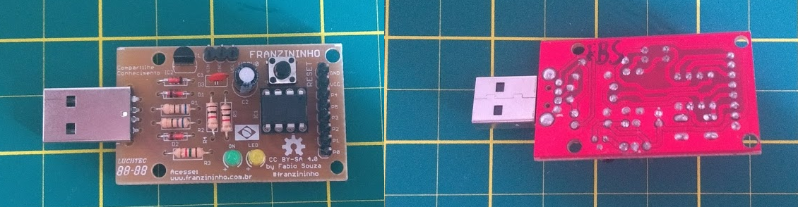
The printed circuit board is responsible for holding all the components. It can be made of fiberglass or phenolic. For the Franzininho DIY, a single-sided design was developed, which allows home manufacturing.
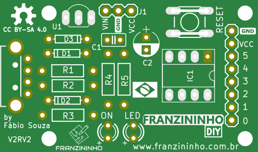
On the top side of the board (TOP) there are component outlines indicating the position of each one. The components are inserted in their respective locations and then soldered through the bottom side (Bottom).
Resistors
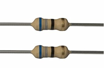
Resistors are passive components that oppose the flow of electric current in the circuit. There are several types of resistors available. In the Franzininho DIY we use 1/4 W carbon resistors. The color bands indicate the resistance value and tolerance.
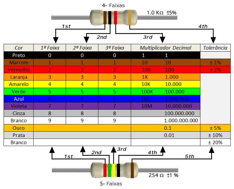
Source: http://blog.render.com.br/eletronica/como-calcular-o-valor-de-um-resistor/
In the Franzininho DIY we use 5 resistors, with the following references and values:
- R1 and R2 - 68 R (Blue, Gray, Black, Gold)
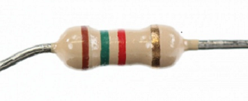
- R3 - 1K5 (Brown, Green, Red, Gold)
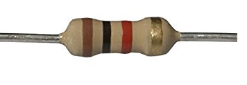
R4 and R5 - 1K (Brown, Black, Red, Gold)
Capacitors
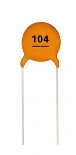
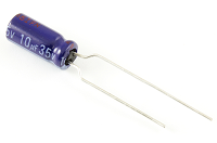
Capacitors are electrical devices capable of storing electric charge in an electric field. In the Franzininho DIY we have 2 types of capacitors:
C1 - Ceramic Capacitor 100 nF x 50 V
C2 - Electrolytic Capacitor 10uF x 35V
LEDs
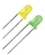
The LED (Light Emitting Diode) is used for light emission in places and instruments where it is more convenient to use instead of a lamp.
In the Franzininho DIY two 3 mm diffused LEDs are used:
ON - Green LED, LED - Yellow LED
Tactile Switch
It is a momentary contact button. In the Franzininho DIY we use a normally open (NO) tactile switch of 4.3 x 6 x 6 mm that serves as the Reset button.
Switch - RESET

Socket
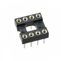
The socket is used to mount integrated circuits, making it easy to replace them on the board.
In the Franzininho DIY we use an 8-pin socket to accommodate the ATtiny85 microcontroller.
IC1 - Socket
Pin Headers
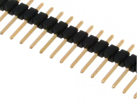
Pin headers are used for pin expansion and power input on the board. In the Franzininho DIY we use 3 pins for the power connector and 8 pins for the board expansion connector.
- J1 - 3-pin header
- P0, P1...GND - 8-pin header
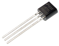
Voltage Regulator
Used to step down the input voltage to a level at which the circuit can operate. In the Franzininho DIY we use a 5V voltage regulator, the 78L05.
IC2 - 78L05 - 5V Voltage Regulator
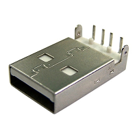
USB Connector
Used to connect the board to a computer or a power supply circuit with a USB connector. In the Franzininho DIY we use a 90° Male USB Connector with latch.
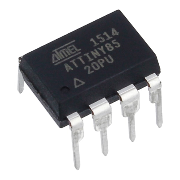
ATtiny85
This is the brain of the Franzininho DIY and the most expensive component. Be careful when inserting it into the socket. Follow the assembly guidelines.