Franzininho DIY Assembly
Step-by-step assembly of the Franzininho DIY V2RV2
Before Getting Started
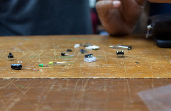
First of all, you should prepare the workspace by gathering the necessary tools for soldering. You will need:
- Soldering iron
- Solder wire
- Diagonal wire cutter for electronics
- Safety glasses
You should also separate the components to make soldering easier. You can find the components in the bill of materials. All organized? Let's go!
Assembling Your Franzininho DIY
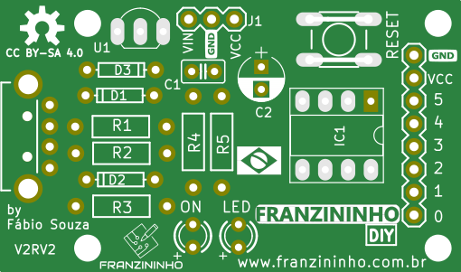
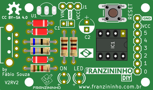
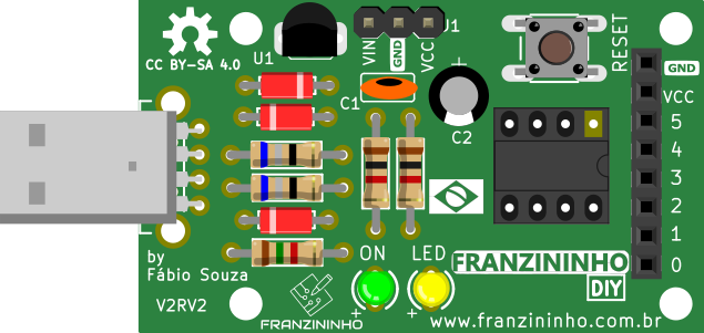
At the start you will have a board without components, as shown in the image below:
You should always start with the shortest components. Follow the recommended sequence below.
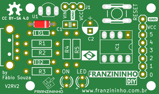
1N4148 Diode
The first component to be placed is the 1N4148 diode at D3.
Be careful about the diode polarity. The black band of the diode must be placed according to the component drawing on the board.
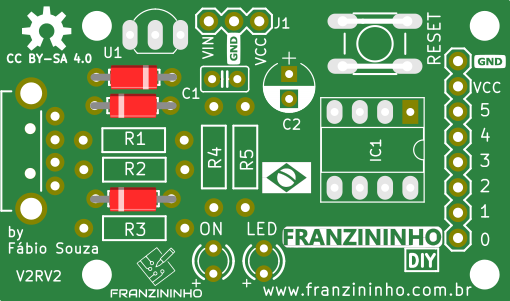
Zener Diodes (3V6)
We have two Zener diodes to be placed at references D1 and D2.
Be careful about the diode polarity. The black band of the diode must be placed according to the component drawing on the board.
68R Resistors
At references R1 and R2 place the 68R resistors represented by the colors (blue, gray, black, and gold).
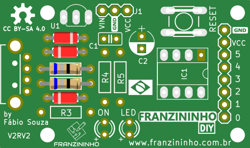
1k5 Resistor
At R3 place the 1k5 resistor represented by the colors (brown, green, red, and gold).
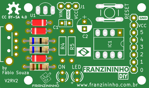
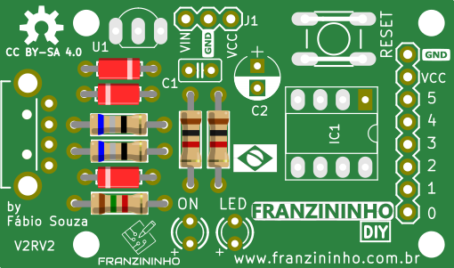
1k Resistors
1k resistors represented by the colors (brown, black, red, and gold) should be placed at R4 and R5.
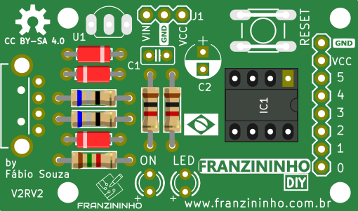
8-pin Socket
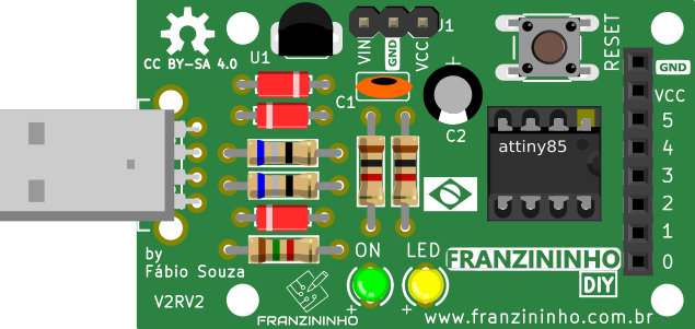
The socket should be placed at IC1 for easy ATtiny85 insertion.
Check the socket position — the half-moon notch must face toward the pin header side of the board.
Tactile Switch
The switch can only be placed in one position, so just fit it where RESET is located.
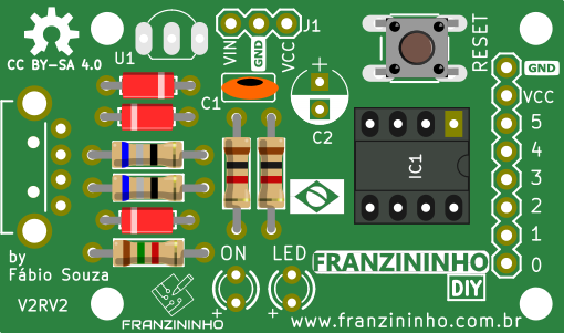
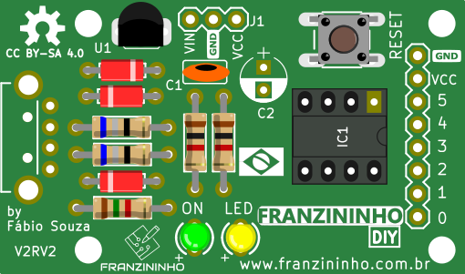
Ceramic Capacitor
At C1 place the ceramic capacitor.
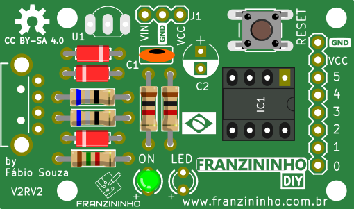
Green LED
The green LED should be placed at ON.
Longer terminal (positive) - Shorter terminal (negative)
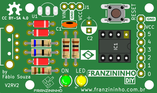
Yellow LED
The yellow LED should be placed at LED.
Longer terminal (positive) - Shorter terminal (negative)
Voltage Regulator
At IC2 place the voltage regulator. It has 3 terminals and must be placed according to the drawing on the board.
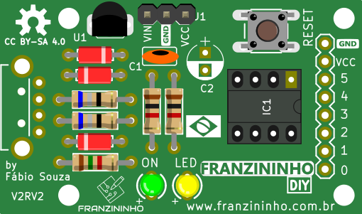
3-pin Header
At J1, indicated by VIN, GND, VCC, place the 3-pin header.
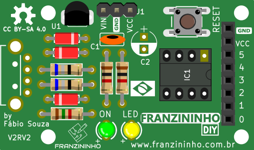
8-pin Header
Should be placed where (GND, VCC, P6, ..., P1, P0) are indicated.
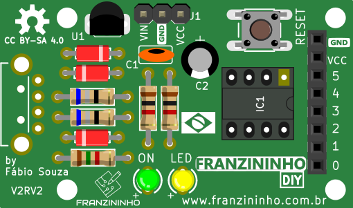
Electrolytic Capacitor
Now place the electrolytic capacitor at C2.
USB Connector
Almost done! Now place the USB connector in its correct orientation.
ATtiny85
Finally, place the ATtiny85 microcontroller in the 8-pin socket.
Done!
Your Franzininho V2RV2 is assembled — now just program it and create many projects.