DHT11 - Temperature and Humidity Sensor
Introduction
In this article, we will explore how to use the DHT11 sensor present on the Franzininho WiFi Lab01 together with an OLED display to create a real-time temperature monitoring system using MicroPython.
We will detail how to collect temperature and humidity data and then display this information on the OLED display along with the date and time. The goal is to have a new update every minute to track changes in the observed environment.
DHT11 Sensor
The DHT11 sensor is a device designed to accurately measure ambient temperature and humidity through a digital output. Embedded in its package is an 8-bit microcontroller, which contributes to the module's high performance.
The main feature of the DHT11 is the NTC resistive element, which is responsible for accurate temperature measurement. This gives the sensor a fast response to environmental variations, as well as excellent resistance to external interference.
The device operates in a temperature measurement range of 0 to 50°C and a humidity range of 20 to 80%.
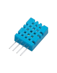
Figure 1 – DHT11 Sensor
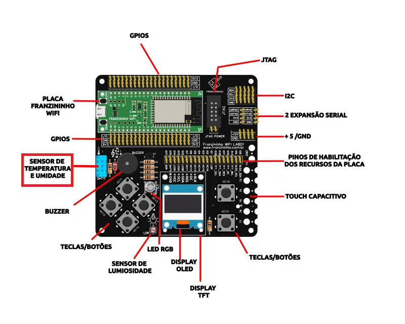
Figure 2 – Location of the DHT11 sensor on the Franzininho WiFi Lab01
Required Resources
To start working with GPIOs, it is essential to have the board pinout available, as this will allow you to identify both the names and functions associated with each pin.
| Pin | Resource |
|---|---|
| IO1 | LDR |
| IO2 | BT6 |
| IO3 | BT5 |
| IO4 | BT4 |
| IO5 | BT3 |
| IO6 | BT2 |
| IO7 | BT1 |
| IO8 | OLED_SDA |
| IO9 | OLED_SCL |
| IO10 | TFT_DC |
| IO11 | TFT_RES |
| IO12 | BLUE LED |
| IO13 | GREEN LED |
| IO14 | RED LED |
| IO15 | DHT11 |
| IO17 | BUZZER |
| IO35 | TFT_SDA |
| IO36 | TFT_SCL |
Table 1 – Franzininho WiFi Lab01 pinout
Uploading the OLED library with Thonny IDE
The library for writing to the OLED display is not part of the standard MicroPython library. Therefore, you need to upload the library to your Franzininho WiFi board in order to use it.
To add the library using Thonny IDE, follow the steps below:
- Create a new file in Thonny and copy the library code:
#MicroPython SSD1306 OLED driver, I2C and SPI interfaces created by Adafruit

import time
import framebuf

# register definitions
SET_CONTRAST        = const(0x81)
SET_ENTIRE_ON       = const(0xa4)
SET_NORM_INV        = const(0xa6)
SET_DISP            = const(0xae)
SET_MEM_ADDR        = const(0x20)
SET_COL_ADDR        = const(0x21)
SET_PAGE_ADDR       = const(0x22)
SET_DISP_START_LINE = const(0x40)
SET_SEG_REMAP       = const(0xa0)
SET_MUX_RATIO       = const(0xa8)
SET_COM_OUT_DIR     = const(0xc0)
SET_DISP_OFFSET     = const(0xd3)
SET_COM_PIN_CFG     = const(0xda)
SET_DISP_CLK_DIV    = const(0xd5)
SET_PRECHARGE       = const(0xd9)
SET_VCOM_DESEL      = const(0xdb)
SET_CHARGE_PUMP     = const(0x8d)


class SSD1306:
    def __init__(self, width, height, external_vcc):
        self.width = width
        self.height = height
        self.external_vcc = external_vcc
        self.pages = self.height // 8
        self.poweron()
        self.init_display()

    def init_display(self):
        for cmd in (
            SET_DISP | 0x00, # off
            SET_MEM_ADDR, 0x00, # horizontal
            SET_DISP_START_LINE | 0x00,
            SET_SEG_REMAP | 0x01, # column addr 127 mapped to SEG0
            SET_MUX_RATIO, self.height - 1,
            SET_COM_OUT_DIR | 0x08, # scan from COM[N] to COM0
            SET_DISP_OFFSET, 0x00,
            SET_COM_PIN_CFG, 0x02 if self.height == 32 else 0x12,
            SET_DISP_CLK_DIV, 0x80,
            SET_PRECHARGE, 0x22 if self.external_vcc else 0xf1,
            SET_VCOM_DESEL, 0x30, # 0.83*Vcc
            SET_CONTRAST, 0xff, # maximum
            SET_ENTIRE_ON, # output follows RAM contents
            SET_NORM_INV, # not inverted
            SET_CHARGE_PUMP, 0x10 if self.external_vcc else 0x14,
            SET_DISP | 0x01): # on
            self.write_cmd(cmd)
        self.fill(0)
        self.show()

    def poweroff(self):
        self.write_cmd(SET_DISP | 0x00)

    def contrast(self, contrast):
        self.write_cmd(SET_CONTRAST)
        self.write_cmd(contrast)

    def invert(self, invert):
        self.write_cmd(SET_NORM_INV | (invert & 1))

    def show(self):
        x0 = 0
        x1 = self.width - 1
        if self.width == 64:
            x0 += 32
            x1 += 32
        self.write_cmd(SET_COL_ADDR)
        self.write_cmd(x0)
        self.write_cmd(x1)
        self.write_cmd(SET_PAGE_ADDR)
        self.write_cmd(0)
        self.write_cmd(self.pages - 1)
        self.write_framebuf()

    def fill(self, col):
        self.framebuf.fill(col)

    def pixel(self, x, y, col):
        self.framebuf.pixel(x, y, col)

    def scroll(self, dx, dy):
        self.framebuf.scroll(dx, dy)

    def text(self, string, x, y, col=1):
        self.framebuf.text(string, x, y, col)


class SSD1306_I2C(SSD1306):
    def __init__(self, width, height, i2c, addr=0x3c, external_vcc=False):
        self.i2c = i2c
        self.addr = addr
        self.temp = bytearray(2)
        self.buffer = bytearray(((height // 8) * width) + 1)
        self.buffer[0] = 0x40
        self.framebuf = framebuf.FrameBuffer1(memoryview(self.buffer)[1:], width, height)
        super().__init__(width, height, external_vcc)

    def write_cmd(self, cmd):
        self.temp[0] = 0x80
        self.temp[1] = cmd
        self.i2c.writeto(self.addr, self.temp)

    def write_framebuf(self):
        self.i2c.writeto(self.addr, self.buffer)

    def poweron(self):
        pass


class SSD1306_SPI(SSD1306):
    def __init__(self, width, height, spi, dc, res, cs, external_vcc=False):
        self.rate = 10 * 1024 * 1024
        dc.init(dc.OUT, value=0)
        res.init(res.OUT, value=0)
        cs.init(cs.OUT, value=1)
        self.spi = spi
        self.dc = dc
        self.res = res
        self.cs = cs
        self.buffer = bytearray((height // 8) * width)
        self.framebuf = framebuf.FrameBuffer1(self.buffer, width, height)
        super().__init__(width, height, external_vcc)

    def write_cmd(self, cmd):
        self.spi.init(baudrate=self.rate, polarity=0, phase=0)
        self.cs.high()
        self.dc.low()
        self.cs.low()
        self.spi.write(bytearray([cmd]))
        self.cs.high()

    def write_framebuf(self):
        self.spi.init(baudrate=self.rate, polarity=0, phase=0)
        self.cs.high()
        self.dc.high()
        self.cs.low()
        self.spi.write(self.buffer)
        self.cs.high()

    def poweron(self):
        self.res.high()
        time.sleep_ms(1)
        self.res.low()
        time.sleep_ms(10)
        self.res.high()
- Go to File > Save as and select the MicroPython device.

- Name the file "ssd1306.py" and click OK to save it to the board.
That's it — the library has been loaded onto your board. You can now use its features in your code by importing the library.
Code
With the Franzininho WiFi Lab01 connected to your computer, open Thonny and create a new file containing the following code:
from machine import Pin, SoftI2C
import ssd1306, dht, framebuf, time

# Franzininho pin assignment
i2c = SoftI2C(scl=Pin(9), sda=Pin(8))

# configuring display
oled_width = 128
oled_height = 64
oled = ssd1306.SSD1306_I2C(oled_width, oled_height, i2c)

# creating symbol to represent degrees on the display
degree = bytearray([0x00, 0x0e, 0x11, 0x11, 0x0e, 0x00, 0x00, 0x00])
fb = framebuf.FrameBuffer(degree, 8, 8, framebuf.MONO_HLSB)

# configuring DHT
d = dht.DHT11(Pin(15))

while True:
    # collecting humidity and temperature data
    d.measure()
    temperature = d.temperature()  # in °C
    humidity = d.humidity()  # in %

    temperature_str = "Temp: " + str(temperature)
    humidity_str = "Humid: " + str(humidity) + " %"

    # collecting current date and time
    current_time = time.localtime()
    formatted_time = "{:02d}/{:02d}/{} {:02d}:{:02d}".format(current_time[2], current_time[1], current_time[0], current_time[3], current_time[4])

    # clear display
    oled.fill(0)

    # display output
    oled.text(formatted_time, 0, 0)
    oled.framebuf.blit(fb, 63, 20)
    oled.text(temperature_str + " " + "C", 0, 25)
    oled.text(humidity_str, 0, 40)
    oled.show()
    time.sleep(60)
We start with from machine import Pin, SoftI2C to be able to access the board pins and use I2C communication to configure the display. Also import the ssd1306 library that was previously installed on your board, and framebuf to use the OLED display.
We also need to import the dht library to work with the DHT11 sensor and time to add delays to the program.
According to the pinout table, the OLED's SCL and SDA pins are pins 9 and 8, respectively. This is how I2C is configured. Then we define the display width and height, which in this case are 128×64. With all this information, create a variable called oled to control the display. This variable receives the OLED width and height as well as the I2C pins we defined earlier.
The display is used to show the temperature and humidity measured by the sensor, as well as the current date and time. However, the display does not support the degree symbol (°) for temperature, so it was necessary to create the symbol using a bitmap.
With the DHT pin configured, inside the loop we start collecting the local temperature and humidity. The measured value is then converted to a string so it can be displayed.
To get the current date and time, we use the localtime function from the time library, which returns the year, month, day, hour, minute, second, day of the week (ranging from 0 to 6, where 0 is Monday and 6 is Sunday), and the day of the year (ranging from 1 to 366). To present this information in a common format, the variable formatted_time was created to organize the date and time in the format dd/mm/yyyy, hh:mm.
The display output starts with the current date and time, followed by the temperature and humidity readings. The bitmap representing the degree symbol (°) is inserted between the temperature value and the Celsius unit (°C).
Every 60 seconds, the temperature and humidity measurements are updated and displayed again on the screen. To ensure the new information is displayed correctly, the display is cleared before each update.
The display output is shown below:
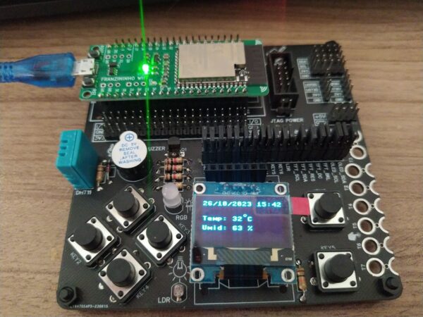
Figure 3 – Display output.
Conclusion
In this article, we saw how to collect temperature and humidity measurements with the DHT11 sensor and how to present this information effectively on an OLED display. We also integrated the display of the current date and time, creating a complete real-time environmental monitoring system with MicroPython.
| Author | Sthefania Fernandes |
|---|---|
| Date: | 17/11/2023 |