Photocell
Introduction
In this article, we will demonstrate how to create a system that operates similarly to street lights. Using a light sensor (LDR), we will control the activation of the RGB LED on the Franzininho WiFi Lab01.
LDR Sensor
The LDR sensor (Light Dependent Resistor), also known as a photoresistor, is a device used to measure the intensity of light present in the environment.
The operation of the LDR sensor is based on the photoconductive effect, which is the ability of some semiconductor materials to change their electrical conductivity when exposed to light. When light hits the LDR sensor material, more electrons are released, increasing the conductivity of the material and decreasing its electrical resistance. On the other hand, in dark environments, fewer electrons are generated, resulting in higher electrical resistance.
They are simple and low-cost devices, so they are very accessible for different projects. However, it is important to note that LDR sensors have some limitations. For example, their accuracy can vary with ambient temperature and humidity conditions.

Figure 1 – LDR Sensor
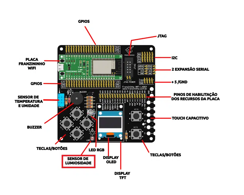
Figure 2 – Location of the LDR sensor on the Franzininho WiFi Lab01
Required Resources
To start working with GPIOs, it is essential to have the board pinout available, as this will allow you to identify both the names and functions associated with each pin.
| Pin | Resource |
|---|---|
| IO1 | LDR |
| IO2 | BT6 |
| IO3 | BT5 |
| IO4 | BT4 |
| IO5 | BT3 |
| IO6 | BT2 |
| IO7 | BT1 |
| IO8 | OLED_SDA |
| IO9 | OLED_SCL |
| IO10 | TFT_DC |
| IO11 | TFT_RES |
| IO12 | BLUE LED |
| IO13 | GREEN LED |
| IO14 | RED LED |
| IO15 | DHT11 |
| IO17 | BUZZER |
| IO35 | TFT_SDA |
| IO36 | TFT_SCL |
Table 1 – Franzininho WiFi Lab01 pinout
Code
With the Franzininho WiFi Lab01 connected to your computer, open Thonny and create a new file containing the following code:
import machine
import utime

led_red = machine.Pin(14, machine.Pin.OUT)  # defining pin 16 as digital output
ldr = machine.ADC(machine.Pin(1))  # defining analog input

conversion_factor = 3.3 / (65535)

while True:
	ldr_reading = ldr.read_u16() * conversion_factor
	utime.sleep(1)
	print(ldr_reading)

	if ldr_reading < 1:
   		led_red.value(1)
	else:
    		led_red.value(0)
Code Explanation
We start with import machine and import utime to be able to access the board pins and to add delays to the program.
Next, we configure the LED and the LDR, where the first will be a digital output and the second an analog input. The pin selection is made according to the pinout table.
Additionally, the value read is converted through a correction factor. This is necessary because the value displayed in the shell is a decimal representation of the raw output of the analog-to-digital converter — but it is not the most friendly way to view it. The conversion factor is the result of dividing two values: the first number is the maximum possible voltage the pin can expect: 3.3V, from the 3V3 output; the second number is the maximum value the analog input reading can have, which is 65535.
With that done, inside a loop we read the sensor using 16-bit precision and multiply by the correction factor. The reading will be collected every 1 second and displayed in the terminal.
Empirically, it was determined that if the value read by the sensor is less than 1, the LED will turn on; otherwise, it will turn off. But I recommend running some tests with your sensor to determine what range you consider appropriate.
Conclusion
The program we created in this article allowed us to develop a system that turns on an LED according to the lighting conditions of the environment, replicating a common situation in automated homes or public street lighting.
| Author | Sthefania Fernandes |
|---|---|
| Date: | 19/01/2023 |