Analog Input
In this example we will learn how to use the Analog-to-Digital Converter (ADC) on the Franzininho WiFi. The goal of this example is to present a simple project to configure the ADC, read the value of an analog input controlled by a potentiometer, and print the conversion value through serial communication. At the end, we will be prepared to perform simple analog readings as well as to use more complex sensors.
Resources
- Franzininho WiFi board
- Potentiometer
- Breadboard
- Jumper wires
- Computer with ESP-IDF installed and configured
Development
A potentiometer is a mechanically operated rotary analog device with 3 terminals that provides a variable amount of resistance when its shaft is rotated. When a voltage is applied to the potentiometer terminals connected to an analog input, we can measure the resistance produced by the potentiometer as an analog value.
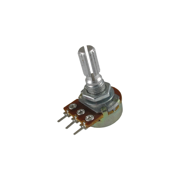
The Analog-to-Digital Converter is a device that converts an analog signal into a digital signal. This example aims to monitor the state of the potentiometer via serial communication, giving us a foundation for working with analog sensors in the future.
Connect the three potentiometer wires to your board. The first wire goes from one of the outer pins of the potentiometer to GND. The second goes from the other outer pin of the potentiometer to 3.3 Volts. And the third goes from the middle pin of the potentiometer to the analog pin GPIO1.
When you rotate the potentiometer, the resistance changes, directly affecting the center pin of the potentiometer and therefore changing the voltage. When the shaft is rotated clockwise the voltage approaches 3.3V; counterclockwise it approaches 0. This voltage is what you are reading at the analog input.
The Franzininho WiFi has 20 ADC inputs: ADC1 has 10 channels configured from GPIO1 to GPIO10, and ADC2 has 10 channels configured from GPIO11 to GPIO20. The analog-to-digital converter of the ESP32-S2 that we will use has 12-bit resolution, so it reads the voltage and converts it to a number between 0 and 4095. The adc1_get_raw() function will capture the amount of voltage applied to the configured channel pin.
Schematic
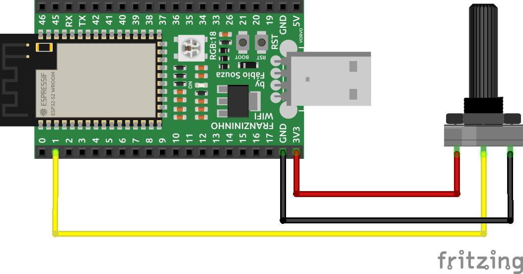
On a breadboard, connect the three potentiometer wires to the Franzininho WiFi. The first goes from one of the outer pins of the potentiometer to GND. The second goes from the other outer pin to 3.3 volts. The third goes from the middle pin of the potentiometer to the analog pin GPIO1.
Code
/*
    Author: Kayann Soares
    Simple usage of Analog Data Reading.
*/

// Required libraries
#include <stdio.h>
#include "sdkconfig.h"
#include "freertos/FreeRTOS.h"
#include "freertos/task.h"
#include "esp_system.h"
#include "esp_spi_flash.h"
#include <driver/adc.h>

// Main
void app_main(){

  // Configure ADC resolution to 13 bits
  adc1_config_width(ADC_WIDTH_BIT_13);
  // Configure ADC Channel to Channel 0
  adc1_config_channel_atten(ADC1_CHANNEL_0,ADC_ATTEN_DB_11);


  while(1){

    // Function to read the analog value on ADC1 (GPIO1)
    int sensorValue = adc1_get_raw(ADC1_CHANNEL_0);

    // Print the read values
    printf("%d\n", sensorValue);

    // 1 second delay routine
    vTaskDelay(1000 / portTICK_PERIOD_MS);
    // Flush output buffers
    fflush(stdout);

  }
}
You can find the complete project at: Analog Input
Build
After coding, let's build the code. First, set the target to ESP32-S2:
idf.py set-target esp32s2
After building, upload the source code to the board. In the editor, press the flash icon and wait a few seconds for the program to start.
![]()
To see the data output of our project, click the monitor icon:
![]()
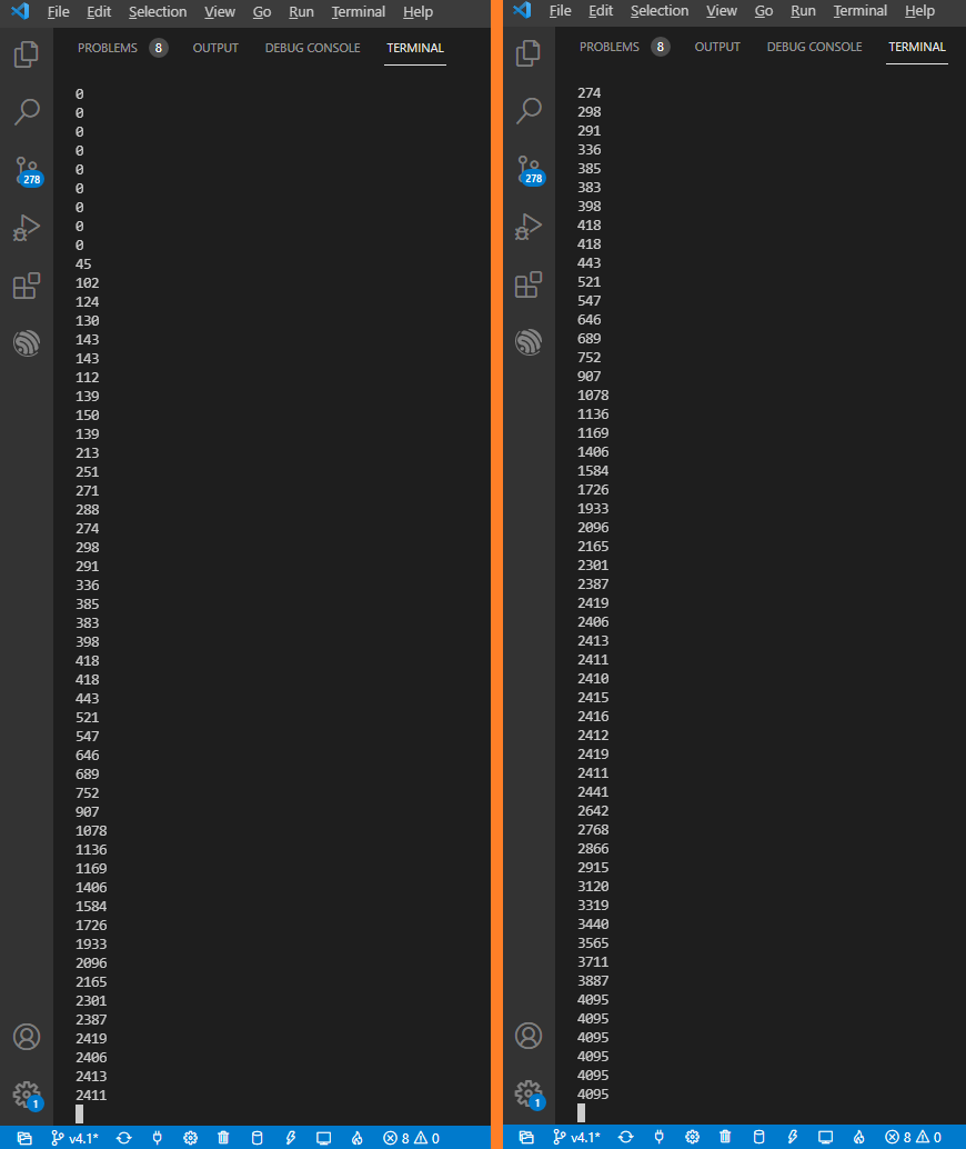
Results
Values shown in the terminal as the potentiometer is rotated.
Conclusion
We have completed the study of the base peripheral to get started with Espressif microcontroller development using the IDF framework. From this article, we can replicate these concepts to other ESP32 families, and they can also be applied to other microcontrollers using C with a more abstract programming style. This article focuses on studying the ADC peripheral. At the end of this project, you will know how to use the Franzininho WiFi ADC for analog data reading, and you are challenged to apply this knowledge to reading analog sensors in your projects using ESP-IDF. Happy studying!
| Author | Kayann Soares |
|---|---|
| Date: | 01/06/2021 |