Digital Input
Continuing with ESP-IDF on the Franzininho WiFi, we will explore GPIO as digital input. The goal is to read the state of the BOOT button (GPIO 0) and use it to control the onboard LED (GPIO 21), while sending status messages over the serial monitor.
By the end you will know how to configure pins as digital input and output, and how to use the ESP32-S2 internal pull-up resistor — no external components required.
Required Resources
- Franzininho WiFi
- Computer with ESP-IDF installed and configured
Development
The program reads the state of the BOOT button connected to GPIO 0 and controls the onboard LED on GPIO 21. The button uses an internal pull-up: when pressed the level is LOW (0), when released it is HIGH (1).
Code
Create a new ESP-IDF project and replace the contents of main.c with the code below:
#include <stdio.h>
#include "freertos/FreeRTOS.h"
#include "freertos/task.h"
#include "driver/gpio.h"

#define BTN 0
#define LED 21

#define ON  1
#define OFF 0

void app_main(void)
{
    gpio_reset_pin(LED);
    gpio_set_direction(LED, GPIO_MODE_OUTPUT);

    gpio_reset_pin(BTN);
    gpio_set_direction(BTN, GPIO_MODE_INPUT);
    gpio_pullup_en(BTN);

    bool last_state_btn = false;

    while (1) {
        bool state_btn = gpio_get_level(BTN);

        if (!state_btn && !last_state_btn) {
            gpio_set_level(LED, ON);
            printf("LED ON\n");
            last_state_btn = true;
        } else if (state_btn && last_state_btn) {
            gpio_set_level(LED, OFF);
            printf("LED OFF\n");
            last_state_btn = false;
        }

        vTaskDelay(1 / portTICK_PERIOD_MS);
        fflush(stdout);
    }
}
The full project is available on GitHub: Button
If you have not yet installed ESP-IDF, see the getting started guide.
Build and Flash
For new projects, configure the console to USB CDC before flashing: Component config → ESP System Settings → Channel for console output → (X) USB CDC
Without this setting, the USB port will not work for monitoring.
Set the target (if you have not done so already):
idf.py set-target esp32s2
Build, flash, and open the monitor in one command (replace /dev/ttyACM0 with your port):
idf.py -p /dev/ttyACM0 flash monitor
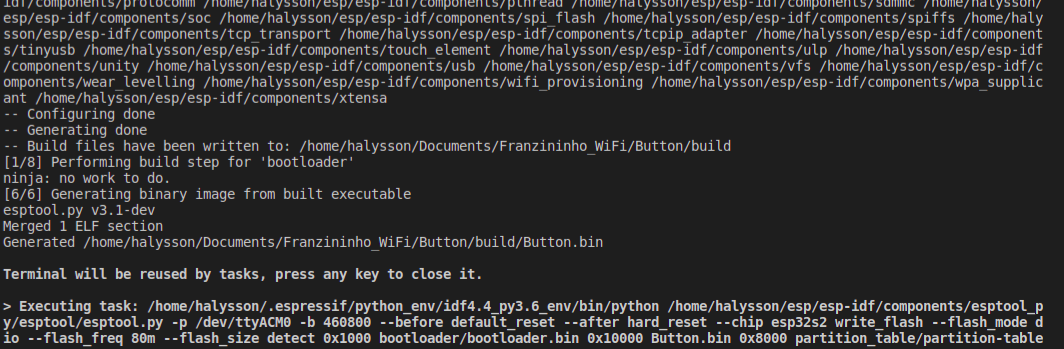
After the build you should see something similar to:
Results
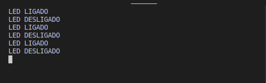
In the serial monitor, press and release the BOOT button to see the output:
Conclusion
With this example you learned how to configure a pin as digital input, apply an internal pull-up resistor in software, and read a button state with gpio_get_level(). The same pattern applies to any digital sensor: vibration, infrared, sound, and more.
Next Steps
- Analog input with ESP-IDF — reading an analog signal with the ESP32-S2 ADC