Hello World! ESP-IDF
In this example we will build the classic "Hello World" with the Franzininho WiFi using ESP-IDF. The goal is to use a GPIO as a digital output, send messages over the serial monitor, and understand the basic structure of an ESP-IDF project.
By the end you will know how to organize a project in ESP-IDF and be ready for the next examples.
Required Resources
- Franzininho WiFi
- Computer with ESP-IDF installed and configured
Development
We will use the Franzininho WiFi to control the onboard LED connected to GPIO 21, toggling it at 1 Hz while sending messages over the serial monitor. If you are coming from Arduino, you will recognize this — it is the Blink sketch with text output.
Code
Create a new ESP-IDF project and replace the contents of main.c with the code below:
#include <stdio.h>
#include "freertos/FreeRTOS.h"
#include "freertos/task.h"
#include "driver/gpio.h"

#define LED 21

char status[2] = {'L', 'H'};

void app_main(void)
{
    gpio_reset_pin(LED);
    gpio_set_direction(LED, GPIO_MODE_OUTPUT);

    printf("Example - Hello World\n");

    int i = 0;

    for (;;) {
        i = i ^ 1;
        gpio_set_level(LED, i);
        printf("Hello World, i am Franzininho WiFi ----> LED status: %c\n", status[i]);
        vTaskDelay(1000 / portTICK_PERIOD_MS);
        fflush(stdout);
    }
}
The full project is available on GitHub: Hello_World
If you have not yet installed and configured ESP-IDF, see the getting started guide.
Build and Flash
For new projects, configure the console to USB CDC before flashing: Component config → ESP System Settings → Channel for console output → (X) USB CDC
Without this setting, the USB port will not work for monitoring.
Set the target (if you have not done so already):
idf.py set-target esp32s2
Build, flash, and open the monitor in one command (replace /dev/ttyACM0 with your port):
idf.py -p /dev/ttyACM0 flash monitor
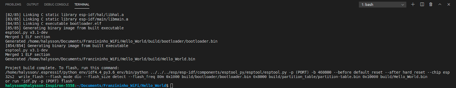
After the build you should see something similar to:
Results
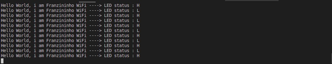
In the serial monitor, the output should look like this:
Conclusion
With this example you learned the basic structure of an ESP-IDF project: includes, pin definitions, app_main(), and the main loop with vTaskDelay(). The function gpio_reset_pin() initializes the pin for GPIO use, and gpio_set_direction() sets its direction.
From here you can apply the same logic to other digital sensors (vibration, infrared, sound) and explore the many other peripherals available on the ESP32-S2.
Next Steps
- Digital input with ESP-IDF — reading a button and controlling an LED