PWM with LEDC
Continuing our ESP-IDF studies, we will now explore a new peripheral: the LED Control (LEDC). Its function is to control the brightness of an LED and also to serve as a pulsed signal generator — Pulse Width Modulation (PWM) — for different purposes such as: speed control in DC motors, angle control in servomotors, color changing in RGB LEDs, and many other applications.
By the end of this article, we will be familiar with the resources offered by this peripheral and will master the basic configuration needed to implement it in projects.
Required Resources
The materials needed for this example are:
- Franzininho WiFi board
- Breadboard
- LED
- 220 Ohm resistor
- Jumper wires
- Computer with ESP-IDF installed and configured
Development
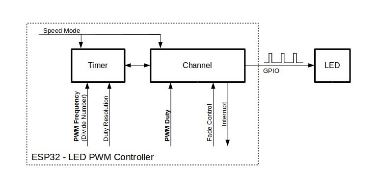
On the Franzininho WiFi board, the LEDC peripheral is organized in two groups of eight channels: one group operating in High Speed Mode (HSM) and another in Low Speed Mode (LSM), operating independently from each other. High Speed mode is implemented in hardware and offers automatic changes without interfering with the PWM duty cycle — if there are timing changes, they will be updated on the next timer overflow. In contrast, Low Speed mode requires explicit software configuration for timing settings.
To use this peripheral, we need to follow some fundamental steps for our study application: Timer Configuration, Channel Configuration, and PWM Modification.
-
Timer Configuration: In this first step we specify the frequency and resolution of the PWM signal by filling in the ledc_timer_config_t data structure and pointing it to the ledc_timer_config() function.
-
Channel Configuration: In this second step we set the GPIO that will be the PWM signal output, which is selected inside the peripheral configuration structure.
-
PWM Modification: In the last step we increase and decrease the duty cycle at the signal generator output, creating a fade effect on the external LED. This will be enabled in hardware by the ledc_fade_func_install() function.
After completing the three configuration steps, the LED Control peripheral will be operational. We now need to assemble the circuit to complete the project.
Schematic
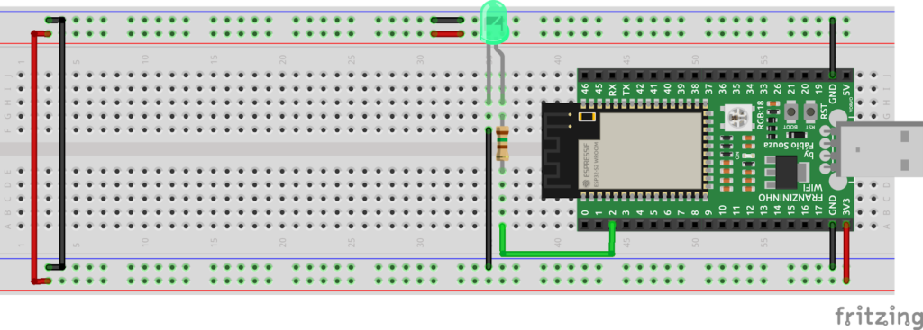
Here we will start assembling the circuit on a breadboard. Connect one terminal of the resistor to GPIO 2 and the other to the external LED.
Below is the proposed schematic:
Code
/*
   Author: Halysson Junior
   Date: 10/04/21

    In this example the LEDC peripheral was configured to control LED brightness.
*/

// Header file includes
#include <stdio.h>
#include "freertos/FreeRTOS.h"
#include "freertos/task.h"
#include "driver/ledc.h"
#include "esp_err.h"

// Definitions for peripheral configuration
#define LEDC_GPIO         2
#define LEDC_FADE_TIME    500
#define LEDC_RESOLUTION   1024
#define LEDC_FREQ         5000


void app_main(void) // Main
{

  // Data structure to receive the configuration variables for frequency (1Hz, 100Hz, etc.), mode (HIGH or LOW) and timer selection (0,1,2)

  ledc_timer_config_t timer = {                   // Timer configuration

      .speed_mode      = LEDC_LOW_SPEED_MODE,     // Speed Mode -> LOW
      .duty_resolution = LEDC_TIMER_10_BIT,       // Duty cycle resolution (2^10 = 1024 values)
      .timer_num       = LEDC_TIMER_0,            // Using TIMER 0
      .freq_hz         = LEDC_FREQ,               // PWM signal operating frequency
      .clk_cfg         = LEDC_AUTO_CLK            // Automatic clock source selection (internal or external)

  };


  ledc_timer_config(&timer); // Sends the timer structure address to the PWM channel configuration function

 /*
   NOTE:
   The PWM frequency and duty cycle resolution are independent. For a high PWM frequency,
   a low duty cycle resolution will be available and vice versa.
 */

 // Data structure to receive configuration variables for frequency (1Hz, 100Hz, etc.), mode (HIGH or LOW), timer selection (0,1,2)

  ledc_channel_config_t channel_LEDC = {
      .gpio_num   =   LEDC_GPIO,             // Select the pin for PWM output
      .speed_mode =   LEDC_LOW_SPEED_MODE,   // Speed Mode -> LOW
      .channel    =   LEDC_CHANNEL_0,
      .timer_sel  =   LEDC_TIMER_0,
      .duty       =   0,
      .hpoint     =   0

    };

  ledc_channel_config(&channel_LEDC);


  ledc_fade_func_install(0); // Initialize the Fade service

  for(;;){ // Loop

   // Set and start the fade function on the LEDC peripheral
    ledc_set_fade_time_and_start( channel_LEDC.speed_mode , channel_LEDC.channel , 0               , LEDC_FADE_TIME , LEDC_FADE_WAIT_DONE);
    ledc_set_fade_time_and_start( channel_LEDC.speed_mode , channel_LEDC.channel , LEDC_RESOLUTION , LEDC_FADE_TIME , LEDC_FADE_WAIT_DONE);


  }// endLoop

}//endMain

/*
 *** Parameters of the "ledc_set_fade_time_and_start();" function ***

ledc_set_fade_time_and_start(ledc_mode_t speed_mode, ledc_channel_t channel, uint32_t target_duty, uint32_t max_fade_time_ms, ledc_fade_mode_t fade_mode)

  ledc_mode_t speed_mode        -> timer mode used
  ledc_channel_t channel        -> LEDC channel index (0-7)
  uint32_t target_duty          -> (2 ** duty_cycle_resolution) - 1
  uint32_t max_fade_time_ms     -> maximum time (ms) for fading
  ledc_fade_mode_t fade_mode    ->
*/
The developed program has a very simple structure and no additional libraries are needed — only the header files already present in the project need to be maintained.
When you create a new project in IDF, configured files are automatically generated and ready for device programming. Type and comment the lines of the following code in the main.c file.
You can find the complete project in the Franzininho documentation: PWM_LEDC
If you have not yet installed and configured IDF on your computer or have questions about the tools, visit the installation tutorial (Click Here).
Build
After coding, let's build the code. First, set the set-target to ESP32-S2. If you don't have the Franzininho WiFi board, change the target to the ESP32 model used in your project.
idf.py set-target esp32s2
At the end of the build, the result should look similar to the image below. If there are errors, go back to the previous steps and review your code.
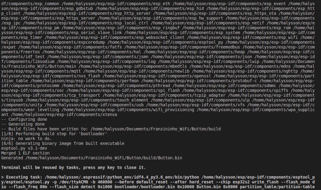
After the build step, upload the source code to the board. In the editor, press the icon below and wait a few seconds to start uploading the "PWM" program (black arrow).

Results
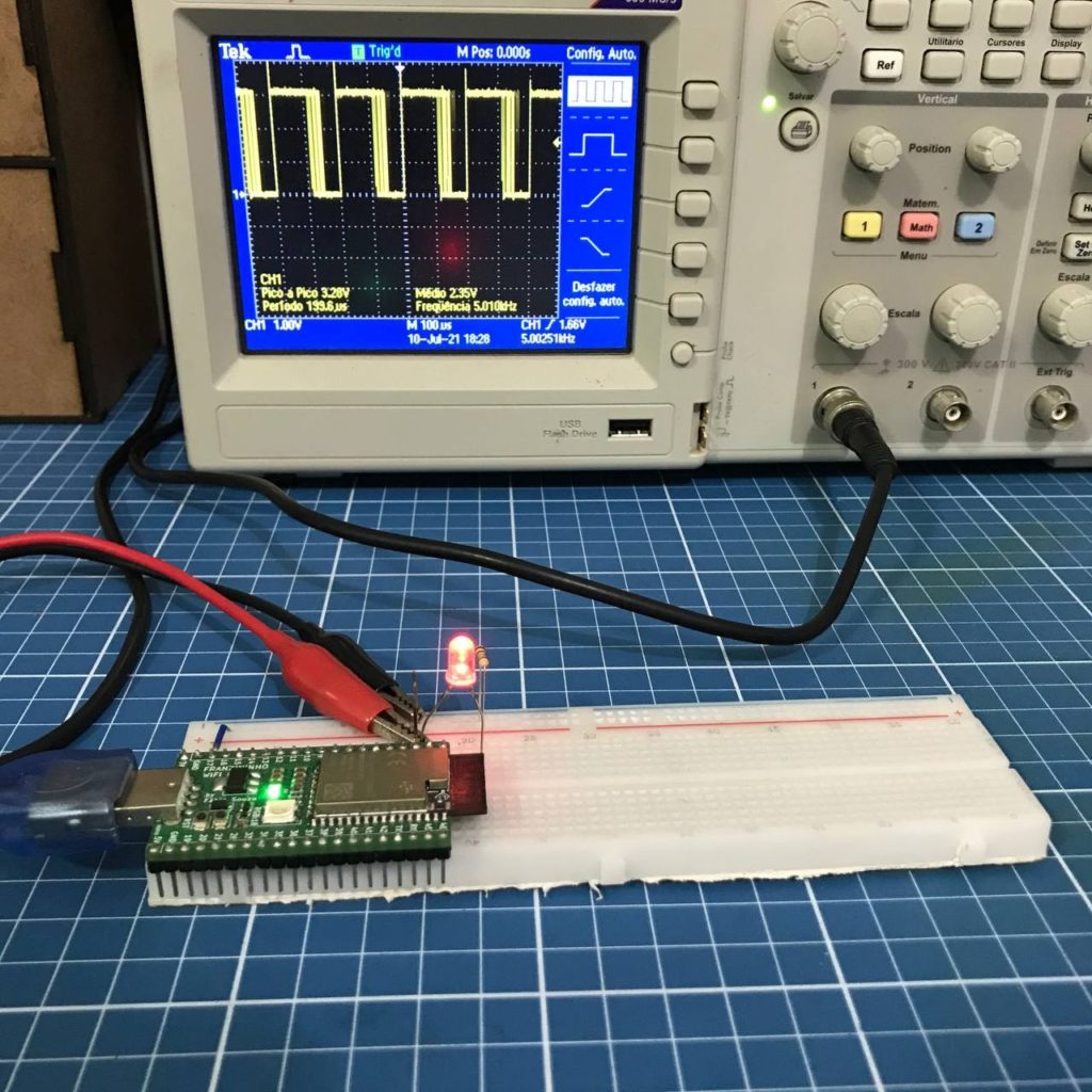
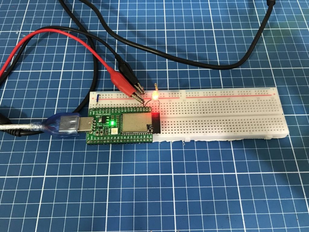
After uploading your code and with the circuit properly assembled, the connected external LED will begin to gradually increase and decrease its brightness, creating the desired fade effect. Figure 5 shows the oscilloscope image displaying the generated waveform and the duty cycle in action; Figure 6 shows the circuit working correctly.
Conclusion
In this example we presented intermediate topics on manipulating the LED Control peripheral, using important C language concepts such as data structures and pointers implemented in the pulsed signal configuration.
This article covers the first steps with this peripheral. We encourage readers to reconfigure the PWM signal output and also consult the documentation provided by Espressif to understand how the chip hardware behaves with each configuration, beyond the functions implemented in software.
| Author | Halysson Junior |
|---|---|
| Date: | 22/07/2021 |