External Pulse Counter
In these three examples we will progressively explore how to make an external event counter on the Franzininho DIY. We will explore the simplest and most complex ways to count events and the advantages of each approach. In these examples we will learn to use the timer and implement debounce, necessary to read only valid events and not count the same event more than once.
Have fun!
Required Resources
- Franzininho DIY (with Micronucleus)
- 4 3mm LEDs
- 4 200Ω resistors
- 1 10kΩ resistor
- 1 tactile switch
- 7 male-female jumpers
- 7 male-male jumpers
Counters
We have three counter examples from version 1 to 3, with increasing code complexity and resources used.
Counter_v1
In this example we will use loops to check for events. This form of counting, while simpler to understand and create, is inefficient both in processing and energy terms.
The program is C language code and uses register names defined in the avr/io.h library. For better understanding, I recommend reading the code comments and the ATtiny85 datasheet.
Code
/**
 * @file main.c
 * @author Eduardo Dueñas
 * @brief Event counter example
 * @version 1.0
 * @date 06/04/2021
 *
 * last modified: 05/05/2021
 */
#include <avr/io.h>

#define F_CPU 16500000L        // CLK frequency

// Macros
#define setBit(value,bit)      (value |= (1 << bit))
#define clearBit(value,bit)    (value &= ~(1 << bit))
#define toggleBit(value,bit)   (value ^= (1 << bit))
#define testBit(value,bit)     (value & (1 << bit))

// Tactile switch debounce to discard button noise and bouncing
char debounce(int pin) {
    unsigned int i;
    for (i = 0; i < 20000; i++) {   // Test the pin multiple times to avoid false readings
      if (!(testBit(PINB, pin))) {  // Test if the pin stopped being 1
          return 0;                 // If so, return false
      }
    }
    return 1;                       // Return true
}

int main(void) {
    // PORTB configuration
    clearBit(DDRB, PB0);       // Configure PB0 as input
    setBit(DDRB, PB1);         // Configure PB1 as output
    setBit(DDRB, PB2);         // Configure PB2 as output
    setBit(DDRB, PB3);         // Configure PB3 as output
    setBit(DDRB, PB4);         // Configure PB4 as output

    PORTB &= 0xE1;             // Send 0 to PB[4:1]

    unsigned char count = 0;

    for (;;) {                    // Infinite loop
        if (testBit(PINB, PB0)) { // Test if PB0 is 1
            if (debounce(PB0)) {  // Verify if it was really a button press
              count++;            // If so, increment counter
              while (testBit(PINB, PB0)) {} // Wait for button to stop being pressed
            }
        }
        count = count % 0x10;     // Clear counter overflow
        PORTB = ((PORTB & 0xE1) | (count << 1)); // Send counter to PB[4:1]
    }
}
Assembly
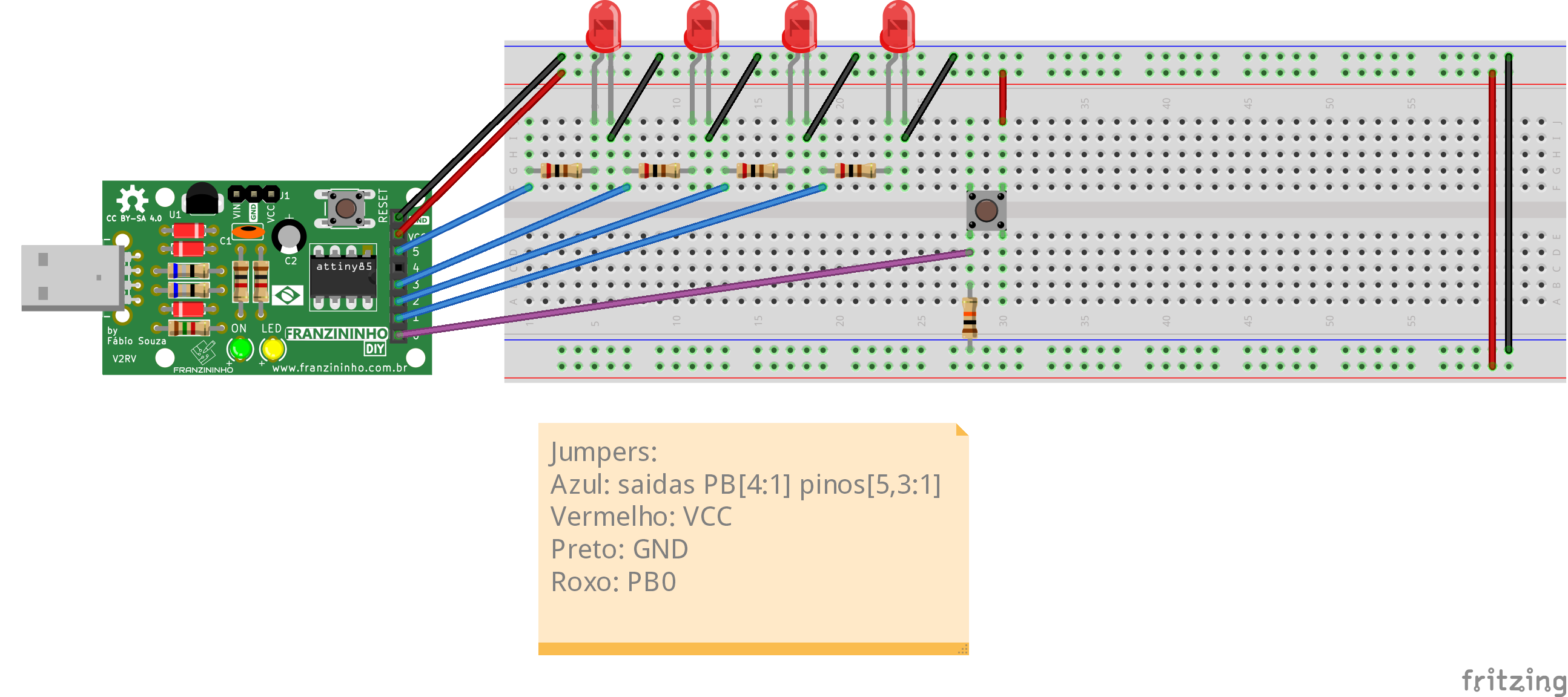
As shown in the image, the LEDs are connected to outputs PortB[4:1] and the button to PortB[0].
Compilation and Upload
To compile the program, as with the previous programs, navigate to the example folder and run the make command:
exemplos-avr-libc/exemplos/contador$ make
Since we already have the makefile configured in the folder, compilation will be done and the following message should appear:
../../micronucleus/2.0a4/launcher  -cdigispark --timeout 60 -Uflash:w:main.hex:i
Running Digispark Uploader...
Plug in device now... (will timeout in 60 seconds)
> Please plug in the device (will time out in 60 seconds) ...
Connect the board to a USB port, or if the Franzininho is already connected, press the reset button to start the upload.
Result
The LEDs should show the button press count in binary, resetting at 0x10 or when the board is reset.
Analysis
This code is simple to understand, using only a for to continuously check whether the button was pressed, calling a debounce function if the reading is 1, incrementing the counter if the reading is confirmed valid, waiting for the button to be released, and sending the value to the outputs.
In general this code works, but there is a lot of processing waste since there are many moments when the processor is doing nothing — just waiting for something to happen or for a certain time to pass. During that time it could be performing other tasks or enter an energy-saving mode, which we will see in upcoming examples.
Counter_v2
In this example we will start using interrupts to read pulses. We will see what the advantages of this method are and what can be improved.
The program is C language code and uses register names defined in the avr/io.h and avr/interrupt.h libraries. For better understanding, I recommend reading the code comments and the ATtiny85 datasheet.
Code
/**
 * @file main.c
 * @author Eduardo Dueñas
 * @brief Event counter example with interrupt handling
 * @version 1.0
 * @date 19/04/2021
 *
 * last modified: 05/05/2021
 *
 * The program is developed on top of counter_v1 with changes to pulse reading
 * using interrupt-based reading, enabling the microcontroller to perform other
 * functions alongside the counter.
 */
#include <avr/io.h>
#include <avr/interrupt.h>

#define F_CPU 16500000L        // CLK frequency

// Macros
#define setBit(value,bit)      (value |= (1 << bit))
#define clearBit(value,bit)    (value &= ~(1 << bit))
#define toggleBit(value,bit)   (value ^= (1 << bit))
#define testBit(value,bit)     (value & (1 << bit))

volatile unsigned char count = 0;   // Counter

ISR(INT0_vect) {
  cli();                       // Disable global interrupts during interrupt handling
  if (debounce(PB2)) {         // If the button was really pressed, increment count and send to LEDs
    count++;                   // Increment counter
    count %= 0x10;             // Clear overflow
    PORTB = ((PORTB & 0xE7) | ((count >> 2) << 3)); // Send two MSBs of count to PB[4:3]
    PORTB = ((PORTB & 0xFC) | (count & 0x03));      // Send two LSBs of count to PB[1:0]
  }
  sei();                       // Re-enable global interrupts
}

// Tactile switch debounce to discard button noise and bouncing
char debounce(int pin) {
  unsigned int i;

  for (i = 0; i < 20000; i++) {   // Test the pin multiple times to avoid false readings
    if (!(testBit(PINB, pin))) {  // Test if the pin stopped being 1
      return 0;                   // If so, return false
    }
  }

  return 1;                       // Return true
}

int main(void) {
    // PORTB configuration
    clearBit(DDRB, PB2);       // Configure PB2 as input
    setBit(DDRB, PB0);         // Configure PB0 as output
    setBit(DDRB, PB1);         // Configure PB1 as output
    setBit(DDRB, PB3);         // Configure PB3 as output
    setBit(DDRB, PB4);         // Configure PB4 as output

    PORTB &= 0xE4;             // Send 0 to PB[4:3] and PB[1:0]

    // External interrupt configuration
    GIMSK |= (1 << INT0);      // Enable external interrupts on INT0
    MCUCR |= 0x03;             // Set interrupts to rising edge
    sei();                     // Enable global interrupts


    for (;;) {                 // Infinite loop
        // Here you can put another application to run simultaneously with the counter
    }
}
Assembly

As shown in the image, the LEDs are connected to outputs PORTB[4:3] and [1:0] and the button to input PORTB[2].
Compilation and Upload
exemplos-avr-libc/exemplos/contador_v2$ make
Result
As in the last example, the LEDs should show the event count in binary up to 15.
Analysis
This example has a slightly more complex code, capable of performing different tasks simultaneously using interrupts.
Interrupts are, simply put, high-priority instructions that make the processor stop what it's doing, save the current state, execute the interrupt instructions, and return to the previous state to continue normally. They are extremely useful for tasks that require high timing precision or asynchronous events.
However, although example two uses interrupts, it spends a lot of time inside them, which delays the progress of another possible program running in main. But most of the time spent in the interrupt is related to the debounce, which basically consists of checks at certain time periods. We can therefore optimize processor usage by exiting the interrupt between checks, since it is just waiting to do the next test. We will see this and the energy-saving mode in counter_v3.
Counter_v3
In this example we will optimize the processing in the code by using interrupts for the debounce waits, and also see an alternative to reduce energy consumption during moments when the processor is waiting for some event — in case you don't need another routine.
This program is C language code and uses register names defined in the avr/io.h and avr/interrupt.h libraries.
Code
/**
 * @file main.c
 * @author Eduardo Dueñas
 * @brief Event counter example with interrupt handling
 * @version 1.0
 * @date 20/04/2021
 *
 * last modified: 05/05/2021
 *
 * The program is developed on top of counter_v2 with changes to the infinite loop
 * (previously left open for other applications) using sleep mode to reduce power
 * consumption and changing the debounce to interrupt-based, increasing code efficiency.
 * The code can be used with other applications in place of the sleep.
 */

#include <avr/io.h>
#include <avr/interrupt.h>
#include <avr/sleep.h>

#define F_CPU 16500000L        // CLK frequency

#define setBit(value,bit)      (value |= (1 << bit))
#define clearBit(value,bit)    (value &= ~(1 << bit))
#define toggleBit(value,bit)   (value ^= (1 << bit))
#define testBit(value,bit)     (value & (1 << bit))

volatile unsigned char count = 0; // Counter
volatile unsigned char test = 0;  // Number of debounce tests

unsigned int pin = 0;             // Debounce pin

// Tactile switch debounce to discard button noise and bouncing
char debounce(int p) {
    pin = p;
    // Set a timer for every 1000 CLK cycles to test the tactile switch
    TCNT0 = 131;               // Overflow-(cycles/Prescaler)=256-(1000/8)=131
    setBit(TIMSK, TOIE0);      // Enable timer overflow interrupts
    test = 0;                  // Clear test
}

ISR(INT0_vect) {               // External pulse interrupt handler
    clearBit(GIMSK, INT0);     // Disable INT0 interrupts during interrupt handling
    debounce(PB2);
}

ISR(TIMER0_OVF_vect) {         // Timer overflow interrupt handler
    TCNT0 = 131;               // Set timer to 131 again
    if (testBit(PINB, pin)) {  // If button is still pressed
        test++;                // Increment test
        if (test >= 20) {      // If tested enough (20 times)
            count++;           // Increment counter
            count %= 0x10;     // Clear overflow
            PORTB = ((PORTB & 0xE7) | ((count >> 2) << 3)); // Send two MSBs to PB[4:3]
            PORTB = ((PORTB & 0xFC) | (count & 0x03));  // Send two LSBs to PB[1:0]
            clearBit(TIMSK, TOIE0); // Disable timer overflow interrupts
            setBit(GIMSK, INT0);    // Re-enable external interrupts on INT0
        }
    }
    else {
      clearBit(TIMSK, TOIE0); // Disable timer overflow interrupts
      setBit(GIMSK, INT0);    // Re-enable external interrupts on INT0
    }
}

int main(void) {
    // PORTB configuration
    clearBit(DDRB, PB2);       // Configure PB2 as input
    setBit(DDRB, PB0);         // Configure PB0 as output
    setBit(DDRB, PB1);         // Configure PB1 as output
    setBit(DDRB, PB3);         // Configure PB3 as output
    setBit(DDRB, PB4);         // Configure PB4 as output

    PORTB &= 0xE4;             // Send 0 to PB[4:3] and PB[1:0]

    // Timer configuration
    TCCR0A = 0x00;             // Normal mode
    TCCR0B = 0x00;
    TCCR0B |= 0x02;            // Prescaler of 8

    // Sleep mode configuration
    clearBit(MCUCR, SM0);      // Configure sleep mode as idle
    clearBit(MCUCR, SM1);

    // External interrupt configuration
    setBit(GIMSK, INT0);       // Enable external interrupts on INT0
    MCUCR |= 0x03;             // Set interrupts to rising edge
    sei();                     // Enable global interrupts

    for (;;) {                 // Infinite loop
      // Here you can put another application to run simultaneously with the counter instead of sleep
      sleep_mode();            // Enter sleep mode
    }
}
Assembly
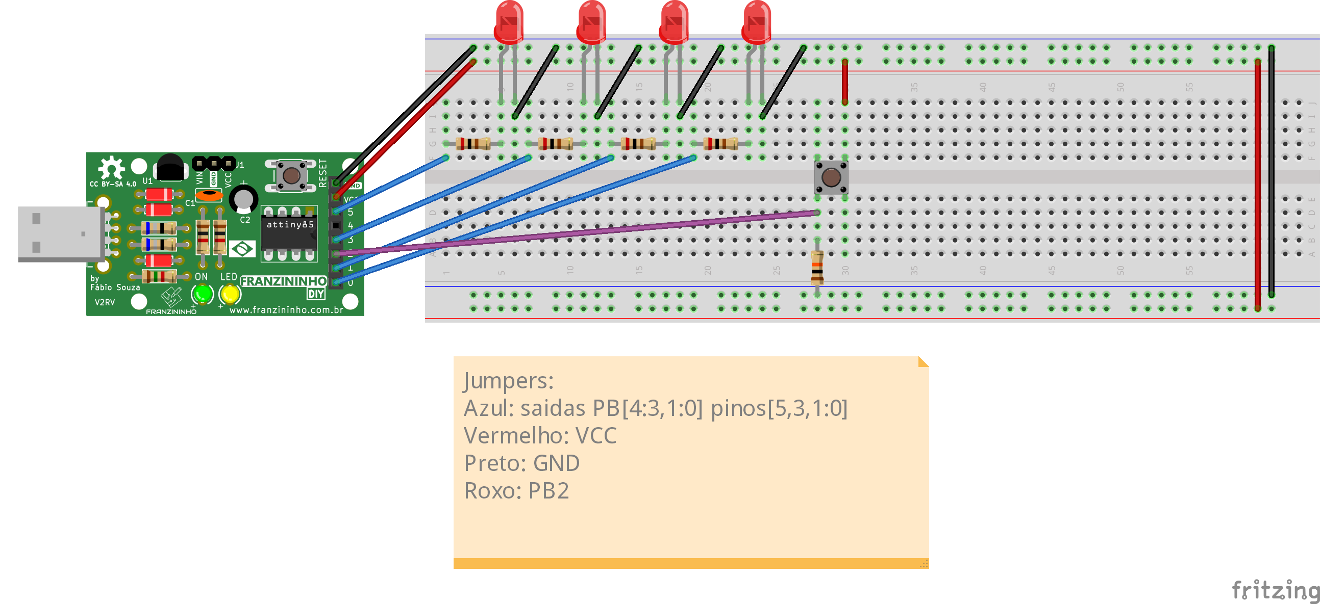
As shown in the image, the LEDs are connected to outputs PORTB[4:3] and [1:0] and the button to input PORTB[2], just as in example two.
Compilation and Upload
exemplos-avr-libc/exemplos/contador_v3$ make
Result
As in the previous examples, the circuit LEDs should show the pulse count up to 15 in binary.
Analysis
In this code we added a bit more complexity, increasing the use of interrupts, plus the use of the timer and Sleep mode.
Sleep mode is an operating mode in which, basically, some modules of the microcontroller are turned off until an interrupt occurs, which can drastically reduce power consumption. In the example code, we use Idle mode which on the ATtiny85 turns off the CPU and FLASH CLKs, with the option to also turn off the ADC CLK.
The timer in this example is configured in normal mode with a prescaler of 8, which makes it increment once every 8 CLK cycles. The method used for time counting was the timer overflow interrupt — i.e., whenever the maximum timer value is reached it generates an interrupt. To get the 1000 cycles we want, we calculate overflow - (cycles/Prescaler), which gives us 256 - (1000/8) = 131, and set the timer to that value so that the desired time remains before the interrupt.
Using timer interrupts for debounce considerably reduces the time the processor spends executing event handler code, which improves the processing of parallel routines, or in this case allows the processor to spend more time in Sleep mode, reducing power consumption — or in battery-powered applications, extending battery life.
Conclusion
In general, all three ways of writing the code work, and since they serve their purpose, none of them are wrong. However, as programmers — especially of embedded systems — it is very good practice to write efficient code so that it does not become an obstacle in the future, whether by using too much memory or making the processor too slow and having to rewrite something from scratch. That is why it is important to know the advantages and disadvantages of each method so we can always use the one that best fits our needs.
Glossary
- Set: place a new value in a register. For a bit, conventionally "set" means changing it to value 1, and "clear" means changing it to value 0.
- Tactile switch/Push button: button
- Debounce: correction of the bouncing effect (effect that occurs in switches that rapidly connect and disconnect before stabilizing)
- Reset: restart
- Timer: electronic circuit dedicated to time counting
| Author | Eduardo Dueñas |
|---|---|
| Date: | 05/05/2020 |