Timer 0
Timers are very important peripherals in microcontrollers. We can use them for timing, event counting, PWM, measuring external pulses, etc. The ATtiny85 has 2 timers, called Timer0 and Timer1. In these examples we will focus on using Timer0 as a timer.
Timer0 Features
Timer0 is a general-purpose 8-bit timer/counter module. This means it can count from 0 to 255. The timing functionality can be further extended using the comparison peripherals, which allow the timer to count events, generate PWM signals, and so on. This makes it possible to generate precise timings, waveforms, and PWM signals independent of the CPU.
The figure below shows the simplified block diagram of Timer0:
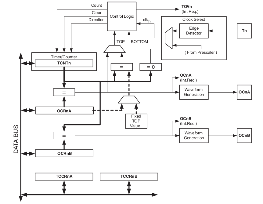
Timer0 Features Summary
- Two independent output compare units
- Double-buffered output compare registers
- Clear timer on compare match (auto-reload)
- Glitch-free, phase correct Pulse Width Modulator (PWM)
- Variable PWM period
- Frequency generator
- Three independent interrupt sources (TOV0, OCF0A, and OCF0B)
Using Timer0 as a Timer
In these examples we will use Timer0 to generate a 1s delay to blink an LED.
Steps to Configure Timer0 as a Timer
Step 1: Configure Timer0 to work in normal mode. In this mode the timer will start counting at 0 and go up to a maximum of 255. When the maximum is reached, an overflow flag is generated and the timer restarts counting from zero.
To configure normal operation mode, we must configure the register TCCR0A – Timer/Counter Control Register A as follows:
- COM0A[1:0] and COM0B[1:0] = 0
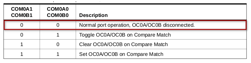
- WGM0[1:0] = 0 and TCCR0B – WGM02 = 0
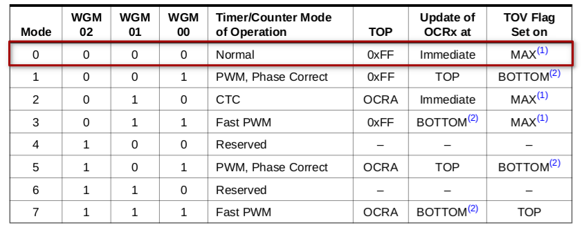
Write the following values to TCCR0A – Timer/Counter Control Register A:
TCCR0A = 0b00000000;
Step 2: Adjust the internal clock prescaler to 1024
To adjust the prescaler, we need to configure bits CS02, CS01, and CS00 of TCCR0B:
- TCCR0B – CS0[2:0]
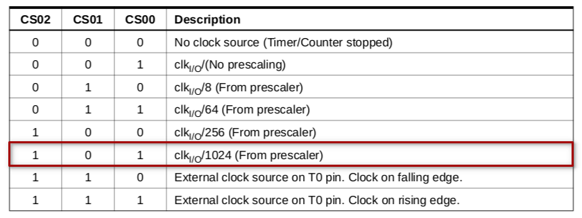
Write the following values to TCCR0B – Timer/Counter Control Register B:
TCCR0B = 0b00000101;
Delay Calculation
We are working with the ATtiny85 internal clock at 16.5 MHz. This is the clock source for Timer0 in normal operation mode. Since we selected the prescaler to divide the clock by 1024, Timer0 increments at:
- time per Timer0 increment = 1/(16.5M/1024) = 62 µs
So the time for Timer0 to overflow is:
- time for Timer0 to overflow = 62µs × 256 = 15.89ms
Therefore, to have a 1-second delay we need:
- number of Timer0 overflows = 1/15.89ms ≃ 63 times
Steps to Monitor Timer Overflow and Generate 1s Delay
- Step 0: Set TCNT0 to zero
- Step 1: Wait for timer count by checking when TOV0 goes to 1
- Step 2: Clear the TOV0 flag by writing 1 to it (yes, writing 1)
- Step 3: Repeat steps 1 and 2 63 times to reach 1 second
- Step 4: One second has passed — Toggle LED
Required Resources
- Franzininho DIY board (with Micronucleus)
- LED
- 470 Ohm resistor
- Jumper wires
- Computer with software tools installed
Example Code
/**
 *
 * @file main.c
 * @author Fábio Souza
 * @brief Shows how to use timer zero for timing
 * @version 0.1
 * @date 2021-02-13
 *
 * @copyright Franzininho
 * This example code is in the Public Domain (or CC0 licensed, at your option.)
 * Unless required by applicable law or agreed to in writing, this
 * software is distributed on an "AS IS" BASIS, WITHOUT WARRANTIES OR
 * CONDITIONS OF ANY KIND, either express or implied.
 *
 */

#include <avr/io.h>
#include <util/delay.h>

#define F_CPU 16500000L

#define setBit(value,bit) (value |= (1<<bit))
#define clearBit(value,bit) (value &= ~(1<<bit))
#define toggleBit(value,bit) (value ^= (1<<bit))
#define testBit(value,bit) (value & (1<<bit))

/**
 * @brief Main function
 *
 * @return int
 */
int main(void)
{

  unsigned char elapsed = 0;  // auxiliary counter

  setBit(DDRB, PB1);  // Configure pin PB1 as output (LED pin)

  // Configure Timer0 to overflow at approximately 15.89ms
  // t = (1/16.5MHz) x 1024 x 256 = 15.89ms
  TCCR0A = 0x00;                     // Normal mode
  TCCR0B = 0x00;
  TCCR0B |= (1<<CS00)|(1<<CS02);    // Prescaler of 1024
  TCNT0 = 0;                         // Initialize timer with 0

  /**
   * @brief Infinite loop
   *
   */
  while (1)
  {
    if (testBit(TIFR, TOV0))         // If timer overflowed
    {
      setBit(TIFR, TOV0);            // Clear flag
      elapsed++;                     // Increment auxiliary counter
      if (elapsed >= 63)             // If 63 x 15.89ms = 1s have passed
      {
        toggleBit(PORTB, PB1);       // Toggle LED
        elapsed = 0;                 // Reset counter
      }
    }
  }
  return (0);
}
Example Simulation
- Wokwi: