Timer 0 - Interrupt
In this example we will understand how to use the Timer0 interrupt to detect its overflow. This way we won't need to monitor the overflow flag in the main application loop.
Timer0 Interrupt
In the previous example we configured Timer0 to operate in normal mode. To monitor its counting, we monitored the TOV0 flag inside the loop. Since the Timer is a peripheral that operates independently of the CPU, we can enable its counting and detect overflow through its interrupt.
To enable the Timer0 interrupt, we must set bit TOIE0 in the TIMSK register to 1:
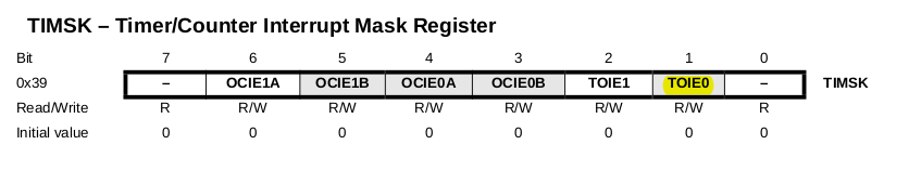
After that, for the interrupt to actually occur, we must enable the global interrupt switch via the sei() function.
Using Timer0 as a Timer with Its Interrupt
Let's make the same application as the previous example: toggling the LED state at 1-second intervals. The difference here is that we will monitor the timer overflows through the interrupt service routine.
The timer configuration is the same, since we want to generate a 1-second delay.
Therefore, we need to count the number of interrupts and when it reaches 63, we will toggle the LED state.
Required Resources
- Franzininho DIY board (with Micronucleus)
- LED
- 470 Ohm resistor
- Jumper wires
- Computer with software tools installed
Example Code
/**
 *
 * @file main.c
 * @author Fábio Souza
 * @brief Shows how to use timer 0 interrupt for timing
 * @version 0.1
 * @date 2021-02-13
 *
 * @copyright Franzininho
 * This example code is in the Public Domain (or CC0 licensed, at your option.)
 * Unless required by applicable law or agreed to in writing, this
 * software is distributed on an "AS IS" BASIS, WITHOUT WARRANTIES OR
 * CONDITIONS OF ANY KIND, either express or implied.
 *
 */

#include <avr/io.h>
#include <util/delay.h>
#include <avr/interrupt.h>

#define F_CPU 16500000L


#define setBit(value,bit) (value |= (1<<bit))
#define clearBit(value,bit) (value &= ~(1<<bit))
#define toggleBit(value,bit) (value ^= (1<<bit))
#define testBit(value,bit) (value & (1<<bit))

unsigned char elapsed = 0;  // auxiliary counter


ISR (TIMER0_OVF_vect) // Timer 0 interrupt vector
{
  elapsed++;                 // Increment auxiliary counter
  if (elapsed >= 63)         // If 63 x 15.89ms = 1s have passed
  {
    toggleBit(PORTB, PB1);   // Toggle LED
    elapsed = 0;             // Reset counter
  }
}

/**
 * @brief Main function
 *
 * @return int
 */
int main(void)
{

  setBit(DDRB, PB1);  // Configure pin PB1 as output (LED pin)

  // Configure Timer0 to overflow at approximately 15.89ms
  // t = (1/16.5MHz) x 1024 x 256 = 15.89ms
  TCCR0A = 0x00;                     // Normal mode
  TCCR0B = 0x00;
  TCCR0B |= (1<<CS00)|(1<<CS02);    // Prescaler of 1024
  TCNT0 = 0;                         // Initialize timer with 0
  setBit(TIMSK, TOIE0);              // Enable Timer0 interrupt
  sei();                             // Enable global interrupt

  /**
   * @brief Infinite loop
   *
   */
  while (1)
  {
    // nothing happens in the loop
  }
  return (0);
}
Note that in the main loop we do nothing. All handling was done in the Timer0 interrupt.
Example Simulation
- Wokwi: