Digital Inputs and Outputs
In the Franzininho DIY we have 6 pins that can be used as digital inputs or outputs (P0 to P5), as shown in the pinout:
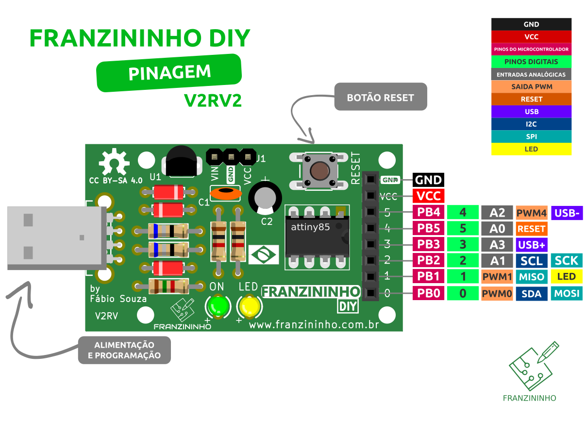
Check pin usage limitations
Configuring the Pin Operating Mode
The ATtiny85 pins can be configured as inputs or outputs, among other functions. To configure as a digital input or output, use the following function:
pinMode()
Configures a specific pin to be a digital input or output.
Syntax:
pinMode(pin, mode);
Parameters:
- pin: the pin you will use. On the Franzininho we can use pins 0 to 5.
- mode: the mode in which you want to configure the pin:
- INPUT = Input: This pin will receive signals from an external circuit
- OUTPUT = Output: This pin will send signals to activate an external circuit
- INPUT_PULLUP = Digital input with internal pull-up resistor (connected to VCC) enabled
Usage Example
Let's configure pin P0 to read a button (digital input) and pin P1 to drive the LED (digital output):
int button = 0;  // button pin
int LED = 1;     // LED pin

void setup() {
  pinMode(button, INPUT); // configure button pin as input
  pinMode(LED, OUTPUT);   // configure LED pin as output
}

void loop() {


}
Generally configurations are done inside the setup() function. Tasks during board operation are performed in the loop() function, as we will see later.
Writing to a Digital Pin
Digital pins configured as digital outputs can take two values, as written in the code. The values can be HIGH or LOW, which translate to 5V or 0V on the Franzininho pin. For digital writing, use the following function:
digitalWrite()
Places a logic HIGH level (HIGH, 5V) or LOW (LOW, 0V) on a pin configured as a digital output.
Syntax
digitalWrite(pin, value)
Parameters
pin: number corresponding to the pin.
value: HIGH or LOW.
Usage Example
Toggles the LED state (P1) at 1-second intervals:
const int LED = 1; // digital pin connected to the LED

void setup(){
  pinMode(LED, OUTPUT); // digital output pin
}

void loop(){
  digitalWrite(LED, HIGH);  // turn on the board LED
  delay(1000);              // wait one second
  digitalWrite(LED, LOW);   // turn off the board LED
  delay(1000);              // wait one second
}
Simulation
The delay(ms) function waits for a time in milliseconds. In the example above, 1000 ms = 1 second.
Reading a Digital Pin
A digital pin can take two values, HIGH and LOW, according to the voltage level present on it: 5V or 0V. We can use a pin configured as a digital input to read sensor states, which in turn represent states of situations, for example:
- button released or pressed
- door open or closed
- object present or not present
To read a digital input, use the following function:
digitalRead()
Reads the value present on a digital pin. This value can be HIGH or LOW.
Syntax
digitalRead(pin);
Parameters:
pin: number of the pin to read.
Return
HIGH or LOW.
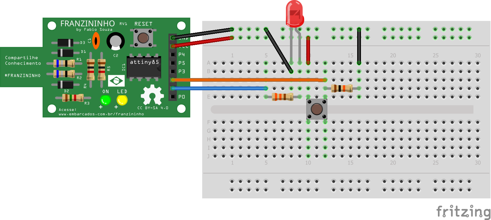
Usage Example
Read the state of the button connected to pin P2 and drive the LED connected to pin P1 according to its state:
Code
const int LED = 1;    // pin for the LED
const int BUTTON = 2; // pin for the button

int val = 0; // val will be used to store the pin state

void setup(){
  pinMode(LED, OUTPUT);    // the LED is an output
  pinMode(BUTTON, INPUT);  // the BUTTON is an input
}

void loop(){
  val = digitalRead(BUTTON); // read and store the input value
  digitalWrite(LED, val);    // drive LED according to button value
}