RGB LED
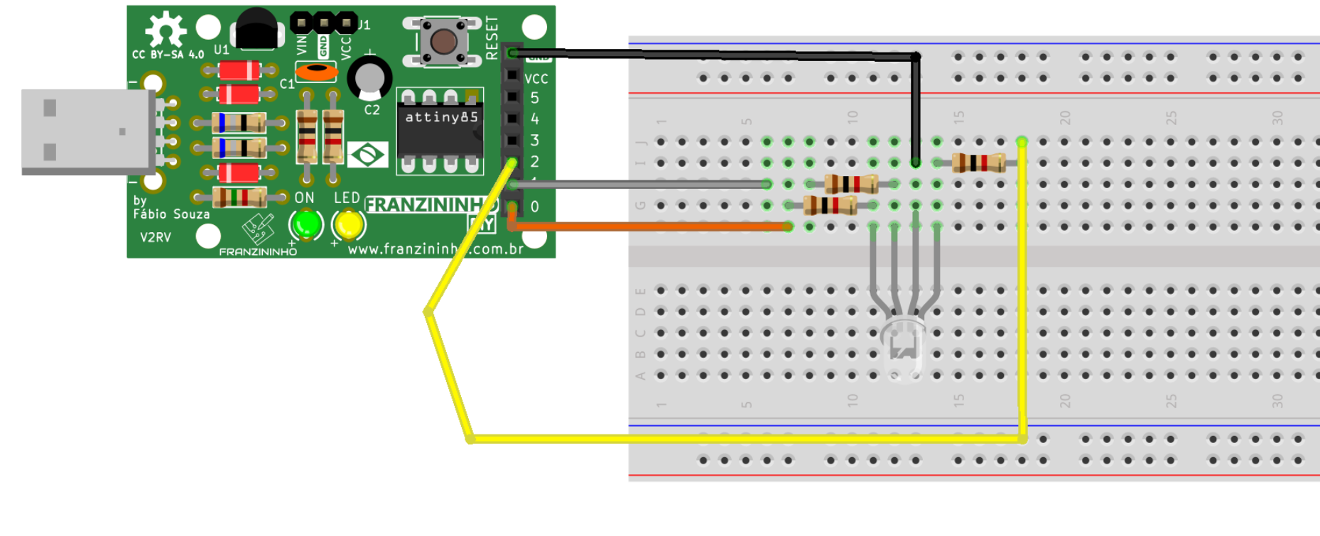
This example teaches how to turn on the RGB LED with the Franzininho DIY in its three colors.
You can control it however you want — check out the simple code in the documentation.
Modify, create, and share!
Materials
- 1 Franzininho DIY board
- 1 Breadboard
- 1 Common cathode RGB LED
- 3 1k resistors
- 3 Male/female jumper wires
Circuit
On the breadboard you can assemble it as follows:
Sketch
// RGB with the Franzininho DIY

const int red = 0;
const int green = 1;
const int blue = 2;

void setup() {
  // configure each color pin as output:
  pinMode(red, OUTPUT);
  pinMode(green, OUTPUT);
  pinMode(blue, OUTPUT);
}

void loop() {
  // activate LED in red color:
  digitalWrite(red, HIGH);
  digitalWrite(green, LOW);
  digitalWrite(blue, LOW);
  delay(5000); // wait 5000ms

  // activate LED in green color:
  digitalWrite(red, LOW);
  digitalWrite(green, HIGH);
  digitalWrite(blue, LOW);
  delay(5000); // wait 5000ms

  // activate LED in blue color:
  digitalWrite(red, LOW);
  digitalWrite(green, LOW);
  digitalWrite(blue, HIGH);
  delay(5000); // wait 5000ms
}