Digital Inputs and Outputs
Now that we understand the basic structure of a CircuitPython program, we will explore the I/O pins as digital input and output. This example shows how to read a button (digital input) and drive an LED (digital output). When the button is pressed, the LED state should be toggled. At the end, we will have an On/Off button to control the LED.
Required Materials
- 1 Franzininho WiFi board with CircuitPython
- 1 Breadboard
- 1 red 3 mm LED
- 1 330 Ω resistor
- 1 Button
- Jumper wires
Circuit
Make the following assembly:
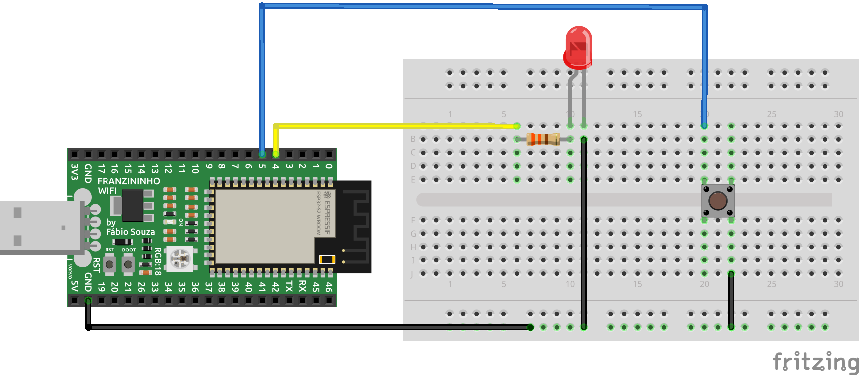
Code
Type the code below in the code.py file inside the CIRCUITPY directory and save the file:
# Digital Inputs and Outputs - On/Off Button
import time
import board
from digitalio import DigitalInOut, Direction, Pull

# Configure the button pin
btn = DigitalInOut(board.IO5)       # map to pin 5
btn.direction = Direction.INPUT     # configure as input
btn.pull = Pull.UP                  # enable internal pull-up


# Configure the LED pin
led = DigitalInOut(board.IO4)       # map to pin 4
led.direction = Direction.OUTPUT    # configure as output

# infinite loop
while True:
	if btn.value ==0:               # If button pressed
		led.value=not led.value     # toggle LED state
		while btn.value==0:         # Wait for button to be released
			time.sleep(0.01)        # 10 ms delay
Code Analysis
To access the board pins we need to import the board module:
import board
Since we need timing intervals, we import the time module:
import time
We will work with digital inputs and outputs in this example. To do that, we need to import the following modules from digitalio:
from digitalio import DigitalInOut, Direction
The button must be configured as a digital input on pin 5. Since we are not using an external pull-up resistor, we must configure the internal pull-up:
# Configure the button pin
btn = DigitalInOut(board.IO5)       # map to pin 5
btn.direction = Direction.INPUT     # configure as input
btn.pull = Pull.UP                  # enable internal pull-up
The LED was configured as a digital output on pin 4, the same way as in the previous example:
# Configure the LED pin
led = DigitalInOut(board.IO4)       # map to pin 4
led.direction = Direction.OUTPUT    # configure as output
In the infinite loop we test the value of the button pin. If it is at level 0, the user pressed it. So every time the button is pressed the LED value is toggled. To avoid multiple operations being triggered, we wait for the user to release the button before reading it again. This wait is done with a while loop:
# infinite loop
while True:
	if btn.value ==0:               # If button pressed
		led.value=not led.value     # toggle LED state
		while btn.value==0:         # Wait for button to be released
			time.sleep(0.01)        # 10 ms delay
Conclusion
In this example, we made a simple application to read a digital input (button) and drive a digital output (LED). This example will serve as a basis whenever you need to work with digital inputs and outputs in your projects. The configuration is always the same.
Add one more button and one more LED to the circuit, working the same way as the one we made.
| Author | Diana Santos |
|---|---|
| Author | Fábio Souza |
| Date: | 16/09/2021 |